3DRE/M(E) Series 3-way Pilot Operated Proportional Pressure Reducing Hydraulic Valve
3DRE/M(E) Series 3-way Pilot Operated Proportional Pressure Reducing Hydraulic Valve
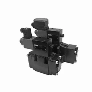
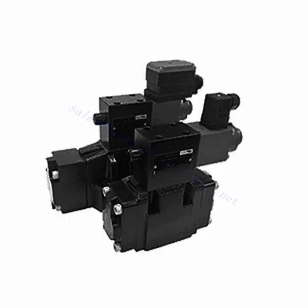
The 3DRE/M(E) series 3-way pilot-operated proportional pressure-reducing hydraulic valve is a cutting-edge hydraulic component designed to deliver accurate pressure control in hydraulic systems. With its advanced pilot-operated proportional control technology, this valve ensures precise regulation, efficient performance, and reliable operation.
The 3DRE/M(E) series 3-way proportional pressure-reducing hydraulic valve empowers hydraulic systems with precise pressure control, efficiency, and reliable performance. With its advanced proportional control technology and 3-way configuration, this valve offers versatility and flexibility in pressure regulation across different hydraulic circuits. By following the recommended usage methods and maintenance guidelines, you can maximize the benefits and longevity of the 3DRE/M(E) series valve, optimizing pressure control and overall performance in your hydraulic system. Upgrade your hydraulic setup today and experience superior pressure regulation with the 3DRE/M(E) series 3-way proportional pressure-reducing hydraulic valve.
3DRE/M(E) Series 3-way Pilot Operated Proportional Pressure Reducing Hydraulic Valve Key Characteristics:
- 比例压力控制:
- The 3DRE/M(E) series valve offers precise and proportional pressure control, enabling dynamic adjustment of hydraulic pressure levels.
- This feature ensures accurate pressure regulation, maintaining a consistent and safe pressure within the hydraulic system.
- Pilot Operated Design:
- With its pilot-operated design, the valve delivers enhanced precision and responsiveness in pressure control.
- It utilizes a pilot valve to modulate the main valve, allowing for precise adjustments and improved control over pressure reduction.
- 三路配置:
- The 3DRE/M(E) series valve features a versatile 3-way configuration, providing flexibility in controlling pressure across different hydraulic circuits.
- It allows for simultaneous pressure reduction in one circuit while supplying pressure to another course.
- 高效性能:
- By utilizing advanced proportional control technology, the valve ensures efficient performance, optimizing energy usage and reducing operational costs.
- It minimizes pressure fluctuations, enhancing system efficiency and contributing to overall productivity.
3DRE/M(E) Series 3-way Pilot Operated Proportional Pressure Reducing Hydraulic Valve Parameter:
| 液压 | ||||||||
| 安装位置 | 可选,最好是水平的 | |||||||
| 尺寸 | 6 | 10 | ||||||
| 重量 | 4WRA…L2X | 公斤 | 2 | 6.6 | ||||
| 4WRAE…L2X | 2.2 | 6.8 | ||||||
| 额定流量qnom,当Δp = 10 bar时 | 升/分钟 | 7、15、26 | 30、60 | |||||
| 滞后 | % | ≤5 | ||||||
| 重复性 | % | ≤1 | ||||||
| 反应敏感度 | % | ≤0.5 | ||||||
| 最大工作压力 | 端口动态血压 | 酒吧 | 315 | |||||
| T 端口 | 酒吧 | 210 | ||||||
| 体液 | 适用于 NBR 和 FKM 密封件的矿物油 | |||||||
| FKM密封用磷酸酯 | ||||||||
| 流体温度范围 | 4WRA…L2X | ℃ | -20℃至70℃(-4°F至158°F) | |||||
| 4WRAE…L2X | ℃ | -20℃至50℃(-4°F至122°F) | ||||||
| 粘度范围 | 毫米²/秒 | 20至380(最好30至46) | ||||||
| 污染程度 | NAS1638 class9 或 ISO 4406 class 20/18/15 | |||||||
| 电气数据 | ||||||||
| 1)螺线管 | ||||||||
| 电压类型 | 直流 | |||||||
| 控制值信号 | ±10V或4~20mA | |||||||
| 每个电磁阀的最大电流 | 一个 | 2.5 | 1.5 | 0.8 | ||||
| 线圈电阻 | 冷值 | Ω | 2 | 4.8 | 19.5 | |||
| 最大保温值 | 3 | 7.2 | 28.8 | |||||
| 责任 | % | ED100% | ||||||
| 线圈温度 | ℃ | 150 | ||||||
| 阀门保护符合 EN 60529 标准 | IP 65 | |||||||
| 2)控制电子元件 | ||||||||
| 放大器 | 4WRA…L2X | VT-VSPA2-L2X | ||||||
| 4WRAE…L2X | 集成在阀门中(OBE) | |||||||
| 工作电压 | 标称电压 | 虚拟数据中心 | 24 | |||||
| 下限值 | 五 | 21/22(4胜4负),19(4胜4负) | ||||||
| 上限值 | 五 | 35 | ||||||
| 放大器电流消耗 | 巨幕 | 一个 | <1.8 | |||||
| 巨幕 | 一个 | 3 | ||||||
3DREP(E)系列三通比例减压液压阀的优点:
• The pilot-operated relief valve is used for the pressure reduction from P to A and the overflow function from A to T.
• Used for bottom sub-plate mounting, driven by proportional solenoid.
• The mounting surface is in accordance with DIN24 340, type A, ISO4401 and CETOP-RP 121H
• The maximum safety pressure is available for selection.
• Spool spring alignmentalignment
• 3DRE electronic controller: european card specification amplifier VT-VSPA1-1/VT-VSPD-1
• Set point the pressure characteristic curve is linear
• 3DRE(M)E series integrated electronic controller
• Setting value caused by manufacturing error-the deviation of the pressure characteristic curve is small
• The slope of the pressure increase and decrease can be adjusted independently
3DREP(E)系列三通比例减压液压阀的使用方法:
- 系统评估:
- 评估您的液压系统,并确定每个回路的具体压力控制要求。
- Determine if the 3DRE/M(E) series valve is suitable based on its pressure range, flow capacity, and compatibility with your system.
- 阀门选择:
- Select the appropriate variant of the 3DRE/M(E) series valve based on your system parameters, pressure range, and flow requirements.
- 考虑最大压力等级、响应时间和运行条件。
- 安装:
- 请仔细遵循制造商的安装说明,确保正确对齐并牢固安装阀门。
- 将阀门连接到液压系统,确保连接无泄漏且流向正确对齐。
- 压力调节:
- Utilize the pilot valve control mechanism provided with the 3DRE/M(E) series valve to adjust the desired pressure reduction level for each circuit.
- Gradually adjust the pilot valve control to achieve the desired pressure control, monitoring the pressure gauge readings and system response.
How To Adjust Hydraulic Valves?
Adjusting hydraulic valves is a crucial task to ensure proper flow control and system performance in hydraulic applications. Here’s a step-by-step guide on how to adjust hydraulic valves:
- Identify the Valve:
- Determine the type of hydraulic valve you need to adjust: pressure relief valve, flow control valve, directional control valve, or any other type.
- Locate the valve within your hydraulic system. It can be positioned near the pump, in the control valve manifold, or within specific hydraulic components.
- 准备必要的工具:
- Before starting the adjustment process, gather the required tools, such as an adjustable wrench, a screwdriver, a pressure gauge (if applicable), and any specialized tools recommended by the valve manufacturer.
- Understand the Valve Function:
- Familiarize yourself with the purpose and function of the valve you are adjusting. Refer to the valve’s technical documentation or consult the manufacturer’s guidelines for specific details.
- Determine the Desired Setting:
- Identify the desired setting or parameter you want to achieve by adjusting the valve. This could be pressure, flow rate, direction, or any other adjustable parameter based on the valve type.
- Preliminary Checks:
- Ensure that the hydraulic system is depressurized before attempting any adjustments. This can be done by shutting down the system and relieving residual pressure through appropriate valves.
- Access the Adjustment Mechanism:
- Locate the adjustment mechanism on the valve. It can be a set screw, locknut, knob, or other similar devices depending on the valve type.
- Some valves may require removing a protective cap or cover to access the adjustment mechanism.
- 逐步调整:
- Using the appropriate tool, make small incremental adjustments to the valve according to the desired setting.
- Follow the manufacturer’s guidelines to determine the direction (clockwise or counterclockwise) and the amount of adjustment required.
- Make gradual adjustments and periodically check the system’s response to ensure you are moving in the desired direction.
- Test and Monitor:
- After each adjustment, activate the hydraulic system and observe its performance.
- Use appropriate measurement tools (pressure gauge, flow meter, etc.) to verify that the valve is operating within the desired range.
- Monitor the system for any abnormalities or unexpected behavior. If necessary, make further adjustments to fine-tune the valve setting.
- Lock the Adjustment (if applicable):
- Once you achieve the desired setting, secure the adjustment mechanism to prevent unintended changes.
- This can be done by tightening a locknut, securing a set screw, or using any other method recommended by the valve manufacturer.
工厂的能力和产能:
(1) 装配
我们拥有一流的自主研发装配平台。液压油缸生产车间拥有 4 条半自动提升油缸装配线和 1 条全自动倾斜油缸装配线,设计年生产能力 100 万支。特种油缸车间配备了各种规格的半自动清洗装配系统,设计年生产能力 20 万只,并配备了知名数控加工设备、加工中心、高精度油缸加工专用设备、机器人焊接机、自动清洗机、油缸自动装配机、自动喷漆生产线等。现有关键设备 300 多台(套)。设备资源的优化配置和高效利用,保证了产品的精度要求,满足了产品的高质量需求。


(2) 机加工
加工车间配备了定制的斜轨车削中心、加工中心、高速珩磨机、焊接机器人及其他相关设备,可加工最大内径 400 毫米、最大长度 6 米的气缸管。

(3) 焊接

(4) 油漆和涂料
配备中小型圆筒自动水性漆喷涂线,实现机器人自动上下料和自动喷涂,设计产能为每班 4000 件;
我们还拥有一条由动力链驱动的大型油缸半自动喷漆生产线,设计产能为每班 60 箱。


(5) 测试
我们拥有一流的检验设施和试验台,确保气缸的性能符合要求。

我们是最好的液压缸制造商之一。我们能够提供全面的液压缸。我们还提供相应的 农用齿轮箱凭借卓越的产品质量和售后服务,我们的产品远销世界各地,赢得了良好的声誉。我们欢迎国内外客户与我们联系洽谈业务、交流信息,并 与我们合作!
液压缸应用:
