4WRZ/H(E)系列先导式比例方向液压阀
4WRZ/H(E)系列先导式比例方向液压阀
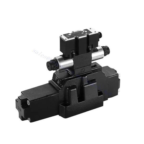
4WRZ/H(E)系列先导式比例方向液压阀是一款先进的液压元件,旨在为液压系统提供卓越的精度、控制性和效率。凭借其先进的先导式比例控制技术,该阀可实现精确的流量调节和无缝的方向切换。
4WRZ/H(E)系列先导式比例换向液压阀为液压系统带来精准的流量控制、灵活的换向功能和卓越的能源效率。其先导式比例控制技术确保了精确灵敏的流量调节,而高流量容量则保证了即使在严苛的应用环境下也能可靠运行。遵循推荐的使用方法和维护指南,您可以最大限度地发挥4WRZ/H(E)系列阀的优势并延长其使用寿命,从而将您的液压系统提升到全新的精度和控制水平。立即升级您的液压系统,体验4WRZ/H(E)系列先导式比例换向液压阀的强大功能。
4WRZ/H(E)系列先导式比例方向液压阀主要特点:
- 先导操作比例控制
- 4WRZ/H(E)系列阀门采用先导式比例控制技术,可根据控制信号进行精确的比例流量调节。
- 该功能可确保精确、灵敏的控制,从而提高系统性能、降低能耗并提高生产效率。
- 多功能方向控制
- 该阀门可灵活控制液压流体方向,适用于多种应用。
- 它能够无缝地激活和停用液压元件(如油缸、马达和执行器)的不同方向,从而增强系统的灵活性和适应性。
- 高流量容量
- 4WRZ/H(E)系列阀门的设计旨在处理高流量,使其成为需要大量液压动力的应用的理想选择。
- 其坚固的结构确保即使在苛刻的条件下也能可靠运行,提供稳定高效的流量控制。
- 能源效率
- 通过采用先导式比例控制,该阀门可最大限度地减少压力损失并优化能源利用。
- 它有助于降低能源消耗,从而节省成本并带来环境效益。
4WRZ/H(E)系列先导式比例方向液压阀参数:
| 一般的 | |||||||
| 阀类型 | WRZ | WRZE | |||||
| 安装 | 可选,最好是水平放置 | ||||||
| 存储温度范围 | ℃ | -20 至 +80 | |||||
| 环境温度范围 | ℃ | -20 至 +70 | -20 至 +50 | ||||
| 重量 | NS 10 | 公斤 | 7.8 | 8 | |||
| NS 16 | 公斤 | 13.4 | 13.6 | ||||
| NS 25 | 公斤 | 18.2 | 18.4 | ||||
| NS 32 | 公斤 | 42.2 | 42.4 | ||||
| 液压 (使用 HLPAG.p=100bar 测量:40 ℃ ± 5 ℃) | |||||||
| 尺寸 | 10 | 16 | 25 | 32 | |||
| 工作压力 | 先导阀 | 外部导油供应 | 酒吧 | 30 至 100 巴 | |||
| 内部引油供应 | 酒吧 | 100 至 350,仅含“D3” | |||||
| 主阀 | 酒吧 | 至 315 | 至350 | 至350 | 至350 | ||
| 回压 | T 口(R 口)(外部先导油排放口) | 酒吧 | 至 315 | 至250 | 至250 | 至 150 | |
| T 口(内部导油排放口) | 酒吧 | 至30 | 至30 | 至30 | 至30 | ||
| Y端口 | 酒吧 | 至30 | 至30 | 至30 | 至30 | ||
| 先导油量输入信号 0-100 % | 厘米3 | 1.7 | 4.6 | 10 | 26.5 | ||
| 输入信号为 0-100 % 时,X 口和 Y 口的先导油流量 | 3.5 | 5.5 | 7 | 15.9 | |||
| 主阀的流量 | 升/分钟 | 至170 | 至460 | 至 870 | 至1600年 | ||
| 液压油 | 升/分钟 | 符合 DIN 51524 标准的矿物油(HL、HLP)。其他油品可按需询价。 | |||||
| 液压油温度范围 | ℃ | -20 至 +80(最好是 +40 至 +50) | |||||
| 粘度范围 | 毫米2/秒 | 20 至 380(最好是 30 至 46) | |||||
| 污染程度 | 压力流体的最大允许污染程度应符合 NAS 1638 或 ISO 4406(c) 标准。 | 建议使用最小截留率βx≥75的过滤器。 | |||||
| 先导阀 | NAS 1638 7 类 | x=5 | |||||
| 主阀 | NAS 1638 9 类 | x=15 | |||||
| 滞后 | % | ≤6 | |||||
| 电气 | |||||||
| 阀类型 | WRZ | WRZE | |||||
| 阀门防护类型符合 EN 60529 标准 | IP65防护等级,电缆插座已安装并锁定 | ||||||
| 电压类型 | 直流 | ||||||
| 命令值重叠 | % | 15 | |||||
| 最大电流 | 一个 | 1.5 | 2.5 | ||||
| 螺线管线圈电阻 | 20℃时的冷值 | Ω | 4.8 | 2 | |||
| 最大保温值 | Ω | 7.2 | 3 | ||||
| 循环持续时间因子 | % | 100 | |||||
| 线圈温度 | ℃ | 至 150 | |||||
| 阀门保护符合 EN 60529 标准 | IP65 | ||||||
| 控制电子设备 | |||||||
| WRZ 型外置放大器 | VT-VSPA2-L2X/… | ||||||
| 控制值信号 | -电压输入“A1” | 五 | ±10 | ||||
| –当前输入“F1” | 毫安 | 4至20 | |||||
4WRZ/H(E)系列先导式比例方向液压阀的优点:
• 先导式两级比例方向阀,用于控制液体流量的大小和方向
• 螺纹连接式比例电磁阀,线圈可单独拆卸
• 底板安装连接结构,连接尺寸符合DIN2430和ISO4401标准
• 阀芯弹簧对准
• WRZE 型,带集成比例放大器
• WRZ型外置放大器(需另行订购)
4WRZ/H(E)系列先导式比例方向液压阀的使用方法:
- 系统评估
- 评估您的液压系统,并确定具体的流量和方向控制要求。
- 根据流量、压力等级以及与系统的兼容性,确定 4WRZ/H(E) 系列阀门是否适合您的系统。
- 阀门选择
- 根据您的系统参数、流量要求和方向控制需求,选择 4WRZ/H(E) 系列阀的合适型号。
- 考虑最大流量、压力等级、响应时间和操作条件等因素。
- 安装
- 请仔细按照制造商的安装说明进行操作,确保阀门正确对准并牢固安装。
- 确保连接处无泄漏,并保证正确的流向对齐,以保证最佳性能。
- 控制信号连接
- 将阀门的控制信号线连接到合适的控制装置,例如比例放大器或电子控制单元。
- 确保阀门与控制装置之间接线正确且兼容,以实现精确、灵敏的控制。
如何排出液压控制阀中的空气?
对液压控制阀进行排气是一项重要的维护程序,用于清除系统中残留的空气或气体,确保其最佳性能和效率。以下是液压控制阀排气的详细步骤:
- 准备系统:
- 务必关闭液压系统并释放压力。这一步骤至关重要,它关系到您的安全,并能防止高压液体意外移动或泄漏。
- 找到液压控制阀上的放气阀或放气螺钉。它通常位于阀体的顶部或侧面,并可能带有保护帽或盖子。
- 定位和安全措施:
- 在排气阀下方放置合适的容器或吸收材料,以收集排气过程中可能排出的任何液体。
- 佩戴合适的个人防护装备(PPE),例如安全护目镜和手套,以保护自己免受液压油飞溅的伤害。
- 打开泄压阀:
- 使用合适的扳手或工具,小心地逆时针方向松开放气阀或螺丝。注意此时不要将其完全拧下。
- 泄压阀可能带有O形圈或密封垫圈。请注意其位置并确保其状况良好。
- 系统激活:
- 打开动力源(例如发动机或液压泵)来启动液压系统。
- 操作与液压控制阀相关的控制机构,例如操纵杆或控制杆,以允许流体流过阀门。
- 出血过程:
- 逆时针方向缓慢打开泄压阀,直到看到液压油或气泡从阀门中逸出。
- 让液体流动几秒钟,或者直到观察到稳定的液流且没有气泡为止。这表明系统中的空气已被排出。
- 注意不要过度打开排气阀,否则可能导致液体过度流失或系统损坏。
- 关闭泄压阀:
- 系统排气完成后,顺时针旋转关闭排气阀。确保拧紧,但避免过度拧紧。
- 检查排气阀或其他连接处周围是否有泄漏。如果发现任何泄漏,请立即处理,以防止出现更严重的问题。
- 系统检查:
- 关闭液压系统,检查油箱内的液位。根据需要添加液压油,以保持推荐液位。
- 测试液压控制阀及其相关部件的运行情况,以确保其功能正常。
工厂的能力和产能:
(1) 装配
我们拥有一流的自主研发装配平台。液压油缸生产车间拥有 4 条半自动提升油缸装配线和 1 条全自动倾斜油缸装配线,设计年生产能力 100 万支。特种油缸车间配备了各种规格的半自动清洗装配系统,设计年生产能力 20 万只,并配备了知名数控加工设备、加工中心、高精度油缸加工专用设备、机器人焊接机、自动清洗机、油缸自动装配机、自动喷漆生产线等。现有关键设备 300 多台(套)。设备资源的优化配置和高效利用,保证了产品的精度要求,满足了产品的高质量需求。


(2) 机加工
加工车间配备了定制的斜轨车削中心、加工中心、高速珩磨机、焊接机器人及其他相关设备,可加工最大内径 400 毫米、最大长度 6 米的气缸管。

(3) 焊接

(4) 油漆和涂料
配备中小型圆筒自动水性漆喷涂线,实现机器人自动上下料和自动喷涂,设计产能为每班 4000 件;
我们还拥有一条由动力链驱动的大型油缸半自动喷漆生产线,设计产能为每班 60 箱。


(5) 测试
我们拥有一流的检验设施和试验台,确保气缸的性能符合要求。

我们是最好的液压缸制造商之一。我们能够提供全面的液压缸。我们还提供相应的 农用齿轮箱凭借卓越的产品质量和售后服务,我们的产品远销世界各地,赢得了良好的声誉。我们欢迎国内外客户与我们联系洽谈业务、交流信息,并 与我们合作!
液压缸应用:
