Rotary Drilling Luffing Cylinder
Rotary Drilling Luffing Cylinder

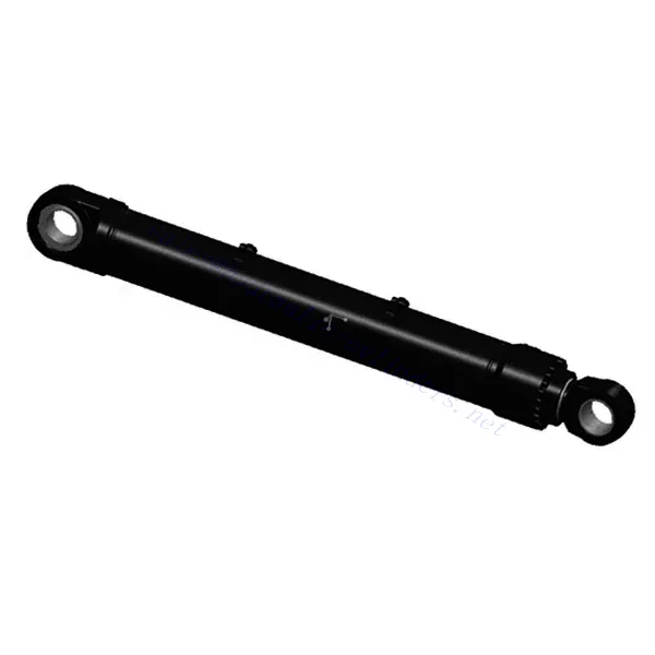
The rotary drilling luffing cylinder is a vital component designed to optimize the performance of rotary drilling equipment. This hydraulic cylinder plays a crucial role in the luffing mechanism, which is responsible for raising and lowering the drilling mast or boom, enabling precise positioning and efficient drilling operations.
The rotary drilling luffing cylinder is a critical component that enhances efficiency and precision in drilling operations. With its robust construction, hydraulic power and control, adjustable luffing range, and smooth movements, this hydraulic cylinder enables operators to position the drilling mast or boom accurately and achieve optimal drilling performance. By following proper usage methods and adhering to recommended maintenance practices, operators can maximize the lifespan and reliability of the rotary drilling luffing cylinder, leading to safe and efficient drilling operations. Choose this indispensable hydraulic component to optimize your drilling equipment and achieve superior results.
Rotary Drilling Luffing Cylinder Key Characteristics:
- Robust Construction and Durability:
- The rotary drilling luffing cylinder is constructed with high-quality materials, ensuring exceptional strength and durability.
- It can withstand the demanding conditions encountered in drilling operations, including heavy loads, vibrations, and harsh environments.
- Hydraulic Power and Control:
- This cylinder operates through a hydraulic control system, utilizing hydraulic power to drive the luffing mechanism.
- The hydraulic control ensures precise and responsive movement of the drilling mast or boom, allowing for accurate positioning and control.
- Adjustable Luffing Range:
- The rotary drilling luffing cylinder provides an adjustable range, enabling operators to position the drilling equipment at the desired angle or height.
- This flexibility allows for versatile drilling operations, accommodating various ground conditions and requirements.
- Smooth and Controlled Movements:
- The cylinder’s design and hydraulic control system ensure smooth and controlled movements during luffing operations.
- This precise control allows operators to maintain stability and accuracy while positioning the drilling mast or boom.
Rotary Drilling Luffing Cylinder Parameter:
| Product Name | Rotary Drilling Luffing Cylinder |
| Features: | Control the luffing angle, adjust the distance between the mast and the host |
| Bore diameter: | 125mm~250mm |
| Rod diameter: | 90mm~160mm Stroke≤1640 mm |
| Pressure: | up to 32MPa |
| Luffing Cylinder Applications: | Rotary Drilling |
Rotary Drilling Luffing Cylinder Identification Diagram:

Usage Method Of Rotary Drilling Luffing Cylinder:
- Familiarize with Controls and Safety Guidelines:
- Before operating the rotary drilling equipment, operators should thoroughly familiarize themselves with the controls and safety guidelines provided by the equipment manufacturer.
- Ensure compliance with all safety procedures and precautions to promote safe and efficient drilling operations.
- Luffing Control:
- Use the control mechanism, such as a joystick or control panel, to activate the Rotary Drilling Luffing Cylinder.
- Apply the appropriate control input to raise or lower the drilling mast or boom to the desired position.
- The cylinder will translate the hydraulic power into the required force to move the equipment smoothly and precisely.
- Positioning and Stability:
- Adjust the luffing range and position of the drilling mast or boom according to the specific drilling requirements and ground conditions.
- Maintain stability during luffing operations to ensure safe and accurate drilling performance.
- Regularly monitor the position of the equipment and make adjustments as necessary to maintain the desired drilling angle or height.
How To Bleed Air From A Hydraulic System?
Bleeding air from a hydraulic system is an important procedure to ensure optimal performance and prevent issues such as sponginess in the hydraulic components. Here’s a step-by-step guide on how to bleed air from a hydraulic system:
- Identify Air in the System:
- Check for symptoms of air in the hydraulic system, such as spongy pedal or lever feel, reduced braking or steering performance, or unusual noises.
- Confirm air presence by inspecting the fluid level in the reservoir. Air bubbles or frothy appearance indicate air in the system.
- Prepare the System:
- Ensure the hydraulic system is turned off and at a safe temperature to avoid potential injuries.
- Locate the bleed valves or fittings in the hydraulic system. These are typically found near the highest points of the system or at components prone to air entrapment, such as calipers or cylinders.
- Gather Necessary Tools:
- Depending on the system, you may need a wrench, socket set, or specialized bleed kit.
- Prepare a container to catch any fluid that may be expelled during the bleeding process.
- Start Bleeding Process:
- Begin with the hydraulic component closest to the reservoir and work your way towards the farthest component.
- Locate the bleed valve or fitting on the first component and position the container to catch the fluid.
- Open the Bleed Valve:
- Using the appropriate tool, slowly open the bleed valve or fitting.
- As fluid is released, air bubbles will escape from the system.
- Purge the Air:
- To purge the air, activate the hydraulic system by pressing the brake pedal, operating the hydraulic lever, or engaging the system as required.
- Repeat this process multiple times, holding the pedal or lever down for a few seconds before closing the bleed valve.
- Close the Bleed Valve:
- Once a steady stream of fluid without air bubbles is observed, close the bleed valve or fitting firmly.
- Ensure it is properly tightened to prevent any leaks.
- Check Fluid Level:
- Monitor the fluid level in the reservoir during the bleeding process.
- Top up the fluid as needed to maintain the recommended level.
- Repeat for Other Components:
- Move to the next hydraulic component in the system and repeat the bleeding process.
- Follow the same steps until all components have been bled.
- Test the System:
- After bleeding all components, test the hydraulic system to ensure proper operation.
- Verify that the pedal or lever feels firm and responsive, and that the system functions as expected.
工厂的能力和产能:
(1) 装配
我们拥有一流的自主研发装配平台。液压油缸生产车间拥有 4 条半自动提升油缸装配线和 1 条全自动倾斜油缸装配线,设计年生产能力 100 万支。特种油缸车间配备了各种规格的半自动清洗装配系统,设计年生产能力 20 万只,并配备了知名数控加工设备、加工中心、高精度油缸加工专用设备、机器人焊接机、自动清洗机、油缸自动装配机、自动喷漆生产线等。现有关键设备 300 多台(套)。设备资源的优化配置和高效利用,保证了产品的精度要求,满足了产品的高质量需求。


(2) 机加工
加工车间配备了定制的斜轨车削中心、加工中心、高速珩磨机、焊接机器人及其他相关设备,可加工最大内径 400 毫米、最大长度 6 米的气缸管。

(3) 焊接

(4) 油漆和涂料
配备中小型圆筒自动水性漆喷涂线,实现机器人自动上下料和自动喷涂,设计产能为每班 4000 件;
我们还拥有一条由动力链驱动的大型油缸半自动喷漆生产线,设计产能为每班 60 箱。


(5) 测试
我们拥有一流的检验设施和试验台,确保气缸的性能符合要求。

We are one of the best hydraulic cylinder manufacturers. We can offer comprehensive hydraulic cylinders. We also provide corresponding 农用齿轮箱. We have exported our products to clients worldwide and earned a good reputation because of our superior product quality and after-sales service. We welcome customers at home and abroad to contact us to negotiate business, exchange information, and 与我们合作!
参观我们的 VR 工厂
通过以下方式参观我们的 VR 工厂
叉车液压缸如何工作?
液压缸应用:
