
4WRKE Series Pilot Operated Proportional Directional Hydraulic Valve
4WRKE Series Pilot Operated Proportional Directional Hydraulic Valve
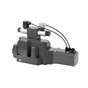
The 4WRKE series pilot-operated proportional directional hydraulic valve is a cutting-edge hydraulic component designed to provide superior precision, control, and efficiency in hydraulic systems. With its advanced pilot-operated proportional control technology, this valve enables accurate flow regulation and seamless directional changes.
The 4WRKE series pilot-operated proportional directional hydraulic valve empowers hydraulic systems with precise flow control, versatile directional changes, and energy efficiency. Its pilot-operated proportional control technology ensures accurate and responsive flow adjustment, while the high flow capacity guarantees reliable performance even in demanding applications. By following the recommended usage methods and maintenance guidelines, you can maximize the benefits and longevity of the 4WRKE series valve, elevating your hydraulic system to new levels of precision and control. Upgrade your hydraulic setup today and experience the power of the 4wrke series pilot-operated proportional directional hydraulic valve.
4WRKE Series Pilot Operated Proportional Directional Hydraulic Valve Key Characteristics:
- Pilot-Operated Proportional Control
- The 4WRKE series valve utilizes pilot-operated proportional control technology, allowing precise and proportional flow adjustment based on control signals.
- Diese Funktion gewährleistet eine präzise und reaktionsschnelle Steuerung, was zu einer verbesserten Systemleistung, einem geringeren Energieverbrauch und einer höheren Produktivität führt.
- Versatile Directional Control
- Dieses Ventil bietet eine vielseitige Steuerung der Hydraulikflüssigkeitsrichtung und ist daher für eine breite Palette von Anwendungen geeignet.
- Es ermöglicht die nahtlose Aktivierung und Deaktivierung hydraulischer Komponenten wie Zylinder, Motoren und Aktuatoren in verschiedene Richtungen und verbessert so die Flexibilität und Anpassungsfähigkeit des Systems.
- High Flow Capacity
- The 4WRKE series valve is engineered to handle high flow rates, making it ideal for applications that require substantial hydraulic power.
- Seine robuste Konstruktion gewährleistet eine zuverlässige Leistung auch unter anspruchsvollen Bedingungen und sorgt für eine konsistente und effiziente Durchflusskontrolle.
- Energieeffizienz
- By incorporating pilot-operated proportional control, this valve minimizes pressure drops and optimizes energy usage.
- Es trägt zur Reduzierung des Energieverbrauchs bei, was zu Kosteneinsparungen und ökologischen Vorteilen führt.
4WRKE Series Pilot Operated Proportional Directional Hydraulic Valve Parameter:
| Allgemein | |||||||||
| Größe | 10 | 16 | 25 | 27 | 32 | 35 | |||
| Installation and commissioning guidelines | optional, vorzugsweise horizontal | ||||||||
| Storage temperature range | ℃ | – 20 to + 80 | |||||||
| Umgebungstemperaturbereich | ℃ | -20 to + 50 | |||||||
| Gewicht | kg | 8.7 | 11.2 | 16.8 | 20 | 37.2 | 72 | ||
| Hydraulisch ( measured at p=100bar,with HLP46 at ϑoil =40℃ ±5℃) | |||||||||
| Betriebsdruck | -Pilot control valve | Pilot oil supply | Bar | 25 to 315 | |||||
| -Main valve | Port P A B | Bar | Up to 315 | Up to 350 | Up to 350 | Up to 210 | Up to 350 | Up to 350 | |
| Return pressure | Anschluss T
(Pilot oil drain) |
Internal | Bar | Static < 10 | |||||
| External | Bar | Up to 315 | Up to 250 | Up to 250 | Up to 210 | Up to 250 | Up to 250 | ||
| Anschluss Y | Bar | Static < 10 | |||||||
| Nominal flow qVnom ±10% at Δp=10bar (Δp = valve pressure differential) |
L/min | 25 50 | – 125 | – 220 | – – | – 440 | – | ||
| 100 | 180 | 350 | 500 | 600 | 1000 | ||||
| Flow of main valve (max. permissible) | L/min | 170 | 460 | 870 | 1000 | 1600 | 3000 | ||
| Pilot oil flow at port X or Y with a step form of input signal from 0 to 100 % (315 bar) | L/min | 4.1 | 8.5 | 11.7 | 11.7 | 13 | 13 | ||
| Druckflüssigkeit | Mineral oil(HL,HLP)to DIN 51 524 Phosphate ester (HFD-R) | ||||||||
| Flüssigkeitstemperaturbereich | ℃ | 10 to 80, preferably 40 to 50 | |||||||
| Viskositätsbereich | mm2/S | 20 to 380, preferably 30 to 45 | |||||||
| Verschmutzungsgrad | Maximum permissible degree of contamination: NAS 1638. | A filter with a minimum retention rate of βx = 75 is recommended | |||||||
| Pilot control valve | Class 7 | x = 5 | |||||||
| Main valve | Class 9 | x = 7 | |||||||
| Hysterese | % | ≤1 | |||||||
| Ansprechsensitivität | % | ≤0,5 | |||||||
| Electrical | |||||||||
| Spannungstyp | Gleichstrom | ||||||||
| Elektrischer Anschluss | Plug-in connector to DIN EN175 201-804 | ||||||||
| Power, max. | W | 72 (average = 24W) | |||||||
| Control electronics | Integrated into the valve | ||||||||
4WRKE Series Pilot Operated Proportional Directional Hydraulic Valve Advantages:
• Pilot-operated two-stage proportional directional valve with electrical position feedback of the main spool, used to control the size and direction of the liquid flow
• Sub-plate mounting type connection structure, connection size conforms to ISO 4401 standard
• Spring centred main spool
• With integrated proportional amplifier
• The pilot control is a single-stage proportional directional valve
• The pilot valve is a threaded proportional solenoid, and the coil can be disassembled separately
Usage Method Of 4WRKE Series Pilot Operated Proportional Directional Hydraulic Valve:
- System Evaluation
- Bewerten Sie Ihr Hydrauliksystem und ermitteln Sie die spezifischen Anforderungen an die Durchfluss- und Richtungssteuerung.
- Determine if the 4WRKE Series Valve is suitable based on its flow capacity, pressure rating, and compatibility with your system.
- Valve Selection
- Select the appropriate variant of the 4WRKE Series Valve based on your system parameters, flow requirements, and directional control needs.
- Berücksichtigen Sie Faktoren wie maximale Durchflussrate, Druckstufe, Reaktionszeit und Betriebsbedingungen.
- Installation
- Befolgen Sie die Installationsanweisungen des Herstellers sorgfältig und achten Sie auf die richtige Ausrichtung und sichere Montage des Ventils.
- Make leak-free connections and ensure the correct flow direction alignment to guarantee optimal performance.
- Control Signal Connection
- Schließen Sie die Steuersignalleitungen des Ventils an ein geeignetes Steuergerät an, beispielsweise einen Proportionalverstärker oder eine elektronische Steuereinheit.
- Sorgen Sie für eine korrekte Verkabelung und Kompatibilität zwischen Ventil und Steuergerät, um eine präzise und reaktionsschnelle Steuerung zu gewährleisten.
How To Clean Hydraulic Valve Lifters?
Cleaning hydraulic valve lifters is an important maintenance task that helps ensure proper engine performance and reduce noise caused by dirt or debris buildup. Here’s a step-by-step guide on how to clean hydraulic valve lifters:
- Sammeln Sie die notwendigen Werkzeuge und Materialien:
- New engine oil
- Saubere Lappen oder Handtücher
- Engine degreaser or parts cleaner
- Small brush or toothbrush
- Plastic container or tray
- Vorbereitung:
- Allow the engine to cool down completely before starting the cleaning process.
- Remove the valve cover or covers to access the hydraulic valve lifters. Refer to the manufacturer’s instructions or a repair manual for your specific engine to locate and remove the valve cover(s) properly.
- Removal of Hydraulic Valve Lifters:
- Identify the hydraulic valve lifters in the engine.
- One at a time, carefully remove the hydraulic valve lifters from their respective locations. Depending on your engine, you may need to remove other components or parts to access the lifters.
- Place each lifter in a plastic container or tray in the order they were removed. This will help ensure they are reinstalled correctly later.
- Cleaning the Lifters:
- Pour a small amount of engine degreaser or parts cleaner into a container.
- Place one hydraulic valve lifter into the container, ensuring it is fully submerged in the cleaner.
- Allow the lifter to soak for the recommended duration specified by the cleaner manufacturer. This usually ranges from 15 minutes to an hour.
- Use a small brush or toothbrush to gently scrub the lifter’s exterior surfaces, removing any deposits or dirt.
- Rinse the lifter thoroughly with clean water to remove any remaining cleaner or debris.
- Dry the lifter using a clean rag or towel. Ensure there are no traces of moisture before reinstallation.
- Reinstallation:
- Apply a small amount of fresh engine oil to the cleaned lifter’s exterior surface.
- Carefully place the lifter back into its original position in the engine, ensuring it is properly aligned and seated.
- Repeat the cleaning process for each hydraulic valve lifter, following the same steps.
- Once all the lifters are cleaned and reinstalled, make sure they are secured properly.
- Zusammenbau:
- Reinstall the valve cover(s) according to the manufacturer’s instructions.
- Double-check that all components and parts are properly secured and tightened.
- Test and Inspection:
- Start the engine and let it run for a few minutes to ensure proper operation and to allow the lifters to refill with oil.
- Listen for any abnormal noises or ticking sounds that could indicate further issues.
- If noise or performance problems persist, it may be necessary to consult a professional mechanic for further diagnosis and repair.
Fähigkeit und Kapazität der Fabrik:
(1) Montage
Wir verfügen über eine erstklassige, unabhängige Forschungs- und Entwicklungsmontageplattform. Die Hydraulikzylinder-Produktionswerkstatt verfügt über vier halbautomatische Montagelinien für Hubzylinder und eine automatische Montagelinie für Kippzylinder mit einer geplanten jährlichen Produktionskapazität von 1 Million Stück. Die Spezialzylinderwerkstatt ist mit verschiedenen Spezifikationen eines halbautomatischen Reinigungsmontagesystems mit einer geplanten jährlichen Produktionskapazität von 200.000 ausgestattet und mit renommierten CNC-Bearbeitungsgeräten, einem Bearbeitungszentrum, einer hochpräzisen Spezialausrüstung für die Zylinderverarbeitung, einer Roboterschweißmaschine, einer automatischen Reinigungsmaschine, einer automatischen Zylindermontagemaschine und einer automatischen Lackierproduktionslinie ausgestattet. Es sind mehr als 300 Sets (Sätze) an kritischer Ausrüstung vorhanden. Die optimale Zuweisung und effiziente Nutzung der Ausrüstungsressourcen gewährleistet die Genauigkeitsanforderungen der Produkte und erfüllt die hohen Qualitätsanforderungen der Produkte.


(2) Bearbeitungen
Die Bearbeitungswerkstatt ist mit einem maßgeschneiderten Schrägschienen-Drehzentrum, einem Bearbeitungszentrum, einer Hochgeschwindigkeits-Honmaschine, einem Schweißroboter und anderen zugehörigen Geräten ausgestattet, die die Bearbeitung von Zylinderrohren mit einem maximalen Innendurchmesser von 400 mm und einer maximalen Länge von 6 Metern ermöglichen.

(3) Schweißen

(4) Malerei und Beschichtung
Mit kleinen und mittleren Zylinder automatische Lackieranlagen auf Wasserbasis, zu erreichen automatische Roboter Be-und Entladen und automatische Spritzen, die Design-Kapazität von 4000 Stück pro Schicht;
Wir verfügen auch über eine halbautomatische Lackieranlage für große Zylinder, die von einer Energiekette angetrieben wird und eine Kapazität von 60 Kisten pro Schicht hat.


(5) Prüfung
Wir verfügen über erstklassige Prüfeinrichtungen und Prüfstände, um sicherzustellen, dass die Leistung des Zylinders den Anforderungen entspricht.

Wir sind einer der besten Hydraulikzylinderhersteller. Wir können umfassende Hydraulikzylinder anbieten. Wir bieten auch entsprechende landwirtschaftliche Getriebe. Wir haben unsere Produkte an Kunden weltweit exportiert und uns aufgrund unserer hervorragenden Produktqualität und unseres Kundendienstes einen guten Ruf erworben. Wir begrüßen Kunden im In- und Ausland, die uns kontaktieren, um Geschäfte zu verhandeln, Informationen auszutauschen und mit uns zusammenarbeiten!


