Vanne hydraulique à débit rapide 2 et 3 voies série WRCE
Vanne hydraulique à débit rapide 2 et 3 voies série WRCE
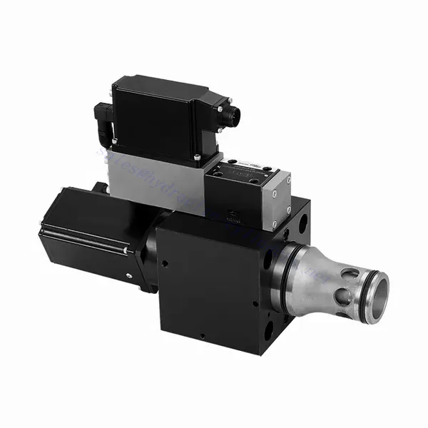
La vanne hydraulique à débit rapide 2 et 3 voies de la série WRCE est un composant hydraulique remarquable, conçu pour offrir des performances exceptionnelles dans les applications de contrôle des fluides. Grâce à son débit rapide, cette vanne révolutionne les systèmes hydrauliques en assurant un contrôle précis et efficace du débit.
La vanne hydraulique à débit rapide 2 et 3 voies de la série WRCE établit de nouvelles normes en matière de précision et d'efficacité du contrôle des fluides. Grâce à son débit rapide, sa conception compacte et sa polyvalence, cette vanne permet aux systèmes hydrauliques d'atteindre des performances et une efficacité énergétique optimales. En respectant les méthodes d'utilisation et les consignes de maintenance recommandées, vous exploiterez pleinement le potentiel de la vanne de la série WRCE et bénéficierez d'un contrôle et d'une productivité accrus dans vos applications hydrauliques. Modernisez votre système hydraulique dès aujourd'hui et profitez des avantages de l'efficacité et de la précision avec la vanne hydraulique à débit rapide 2 et 3 voies de la série WRCE.
Caractéristiques principales des vannes hydrauliques à débit rapide 2 et 3 voies de la série WRCE :
- Flux à réponse rapide :
- La vanne de la série WRCE est conçue pour offrir un contrôle de débit à réponse rapide, garantissant des ajustements rapides et précis des débits de fluide.
- Cette caractéristique permet un contrôle précis des actionneurs hydrauliques, ce qui améliore les performances du système, réduit la consommation d'énergie et augmente l'efficacité globale.
- Configuration polyvalente à 2 et 3 voies :
- Cette vanne est disponible en configurations à 2 et 3 voies, offrant ainsi la flexibilité nécessaire pour répondre aux diverses exigences des systèmes hydrauliques.
- La configuration à 2 voies permet une simple commande marche/arrêt, tandis que la conception à 3 voies permet un contrôle directionnel, ce qui la rend idéale pour des applications telles que l'extension et la rétraction de l'actionneur.
- Conception compacte :
- La vanne de la série WRCE présente une conception compacte, ce qui la rend adaptée aux installations où l'espace est limité.
- Sa taille compacte permet une intégration facile dans divers systèmes hydrauliques sans compromettre les performances ni la fonctionnalité.
- Pression nominale élevée :
- Cette vanne est conçue pour résister aux environnements à haute pression, garantissant un fonctionnement fiable même dans les applications hydrauliques exigeantes.
- Sa construction robuste et sa résistance à la haute pression le rendent adapté aux systèmes nécessitant un contrôle efficace du débit dans des conditions de fonctionnement extrêmes.
Paramètres des vannes hydrauliques à débit rapide 2 et 3 voies de la série WRCE :
| Général | |||||
| NS NG | 32 | 40 | 50 | ||
| Poids | kg | 11.2 | 17.3 | 24.6 | |
| Weight with shut-off valve …../…WK or …/…WL… | kg | 12.5 | 18.6 | 25.9 | |
| Dimension de la vanne de commande pilote (pilote) | NG | 6 | 6 | 6 | |
| Position d'installation | N'importe lequel, de préférence horizontal | ||||
| Plage de température de stockage | °C | –20 à +80 | |||
| Plage de température des circonstances | °C | –20 à +50 | |||
| Hydraulique (mesuré avec HLP32, ϑhuile=40℃ ±5℃) | |||||
| Pression de service max. | – Scène principale Port A, B | bar | NS 32~40 : 350, NS 50 : 420 | ||
| – Orifice de la vanne de commande pilote X | 315 | ||||
| – Orifice de la vanne de commande pilote Y | 210 | ||||
| Débit nominal Δp = 5 bar | – Specifications …S…L (linear) | L/min | 800 | 1200 | 2000 |
| – Specifications …S…R (linear with progressive fine control range) | 600 | 850 | 1400 | ||
| Débit nominal de la vanne pilote à Δp = 70 bar | L/min | 12 | 40 | 40 | |
| Fuite de la vanne pilote à P=100 bar | L/min | 0.3 | 0.7 | 0.7 | |
| fluide hydraulique | Huile minérale (HL, HLP) conforme à la norme DIN 51524 | ||||
| Plage de température du fluide hydraulique | °C | 20 à +80 ; de préférence de +40 à +50 | |||
| Plage de viscosité | mm2/s | 20 à 380 ; de préférence 30 à 45 | |||
| Degré maximal admissible de contamination du fluide hydraulique, classe de propreté selon ISO 4406 (c) | Classe 20/18/15 | ||||
| Hystérèse | % | ≤ 0,2 | |||
| Hystérèse | % | ≤ 0,1 | |||
| Sensibilité de la réponse | % | ≤ 0,1 | |||
| Temps de réponse (pas de signal 0 ~ 100%) | MS | ≤ 20 | |||
| données électriques | |||||
| Type de tension | Tension continue | ||||
| Type de signal | Analogique | ||||
| Calibrage du point d'ouverture | % | ≦ 1 | |||
| Décalage nul lors du changement de : | – Température du fluide hydraulique | %/10K | ≦ 0,3 | ≦ 0,3 | ≦ 0,3 |
| – Pression pilote en X | %/100 bar | ≦ 0,7 | ≦ 0,7 | ≦ 0,7 | |
| – Pression de retour en Y | %/bar | ≦ 0,3 | ≦ 0,3 | ≦ 0,3 | |
| Classe de protection de la vanne selon la norme EN60529 | IP65 avec connecteur d'accouplement monté et verrouillé | ||||
Avantages des vannes hydrauliques à débit rapide 2 et 3 voies de la série WRCE :
• Vanne d'étranglement à cartouche à deux étages à réponse haute fréquence, commandée par pilote
• Convient à la commande en boucle fermée de la position, de la pression, de la force et de la vitesse
• Vanne de commande pilote : vanne proportionnelle à six voies à action directe et à réponse haute fréquence avec retour électrique
• Étape principale : contrôle de position en boucle fermée
• Électronique de commande intégrée en boucle ouverte et en boucle fermée (OBE)
Mode d'emploi de la vanne hydraulique à débit rapide 2 et 3 voies de la série WRCE :
- Évaluation du système :
- Évaluez votre système hydraulique et déterminez les exigences spécifiques en matière de contrôle du débit.
- Déterminez si la vanne de la série WRCE est compatible avec votre système en fonction de facteurs tels que les débits, les pressions nominales et les fonctions de contrôle souhaitées.
- Sélection de la vanne :
- Sélectionnez la variante appropriée de la vanne de la série WRCE en fonction des paramètres de votre système et de vos besoins en matière de contrôle de débit.
- Tenez compte de facteurs tels que le débit, la pression nominale, le temps de réponse et la compatibilité avec votre application spécifique.
- Installation:
- Follow the manufacturer’s installation instructions carefully to ensure proper alignment and secure mounting of the valve.
- Veillez à réaliser des raccords étanches en utilisant des raccords hydrauliques, des adaptateurs et des joints adaptés. Serrez correctement les raccords afin d'éviter toute fuite de fluide.
- Intégration des signaux de commande :
- Raccordez les lignes de signal de commande de la vanne à un dispositif de commande approprié, tel qu'un module de commande hydraulique, une unité de commande électronique ou un levier de commande manuel.
- Assurez-vous d'un câblage correct et d'une compatibilité entre la vanne et le dispositif de commande pour obtenir un contrôle de débit précis et réactif.
Comment raccorder une vanne de commande hydraulique ?
Pour raccorder une vanne de commande hydraulique, suivez ces étapes :
- Identifier le type de vanne : Déterminez le type précis de distributeur hydraulique que vous utilisez : distributeur directionnel, régulateur de pression ou régulateur de débit. Assurez-vous que le distributeur est adapté à votre application et compatible avec votre système hydraulique.
- Rassemblez les outils et matériaux nécessaires : Collect the necessary tools and materials, including appropriate hydraulic fittings, adapters, hoses, and wrenches. Refer to the manufacturer’s instructions for any specific tools or components needed.
- Préparez le système hydraulique : Arrêtez le système hydraulique et relâchez la pression en activant la soupape de décharge ou en rétractant les vérins hydrauliques. Cette étape est cruciale pour la sécurité et empêche tout mouvement accidentel ou toute fuite de liquide hydraulique.
- Identifier le sens du flux : Déterminez le sens d'écoulement dans votre système hydraulique. Généralement, ce sens est indiqué par des flèches sur les composants hydrauliques. Assurez-vous de bien comprendre le sens d'écoulement avant de poursuivre.
- Localiser le point d'installation : Déterminez l'emplacement optimal pour installer le distributeur hydraulique dans votre système hydraulique. Tenez compte de facteurs tels que l'accessibilité, la proximité de l'actionneur ou du composant hydraulique et la facilité d'utilisation. Assurez-vous qu'il y a suffisamment d'espace pour fixer solidement le distributeur.
- Monter la valve : Securely mount the hydraulic control valve in the chosen location using appropriate brackets or clamps. Ensure the valve is positioned correctly, aligning the inlet and outlet ports with the flow direction. Follow the manufacturer’s instructions for the specific mounting requirements of your valve.
- Connectez les ports d'entrée et de sortie : Raccordez les flexibles ou tubes hydrauliques aux orifices d'entrée et de sortie du distributeur hydraulique. Utilisez des raccords et adaptateurs hydrauliques adaptés pour garantir l'étanchéité. Serrez les raccords à l'aide de clés pour assurer une fixation sûre, sans toutefois trop serrer.
- Raccordez les lignes de commande : If your hydraulic control valve requires external control signals, connect the control lines from the control device, such as a joystick, lever, or solenoid, to the appropriate ports on the valve. Follow the manufacturer’s instructions for the correct wiring or connection configuration.
- Tester le système : Une fois le distributeur hydraulique installé, rétablissez lentement la pression du système hydraulique. Testez le système pour vérifier le bon fonctionnement du distributeur. Actionnez le dispositif de commande et observez la réaction des composants hydrauliques afin de vous assurer que le distributeur régule le débit, la pression ou la direction comme prévu.
- Réglages et ajustements : Make any necessary adjustments to the hydraulic control valve to achieve the desired flow, pressure, or direction control. Refer to the manufacturer’s instructions for specific adjustment procedures. Regularly monitor the system for any leaks, pressure inconsistencies, or abnormal behavior.
Capacité de l'usine :
(1) Assemblage
Nous disposons d'une plateforme d'assemblage indépendante de recherche et développement de premier ordre. Notre atelier de production de vérins hydrauliques dispose de quatre lignes d'assemblage semi-automatiques de vérins de levage et d'une ligne d'assemblage automatique de vérins d'inclinaison, pour une capacité de production annuelle prévue d'un million de pièces. L'atelier de vérins spéciaux est équipé d'un système d'assemblage de nettoyage semi-automatique de diverses spécifications, d'une capacité de production annuelle prévue de 200 000 pièces et dispose d'équipements d'usinage CNC de pointe, d'un centre d'usinage, d'équipements spéciaux d'usinage de haute précision, d'une machine de soudage robotisée, d'une machine de nettoyage automatique, d'une machine d'assemblage automatique de vérins et d'une ligne de peinture automatique. Nous disposons de plus de 300 équipements critiques. L'allocation optimale et l'utilisation efficace des ressources garantissent la précision et la qualité des produits.


(2) Usinage
L'atelier d'usinage est équipé d'un centre de tournage sur rail incliné personnalisé, d'un centre d'usinage, d'une machine à honer à grande vitesse, d'un robot de soudage et d'autres équipements connexes, qui peuvent traiter des tubes cylindriques d'un diamètre intérieur maximal de 400 mm et d'une longueur maximale de 6 mètres.

(3) Soudage

(4) Peinture et revêtement
Avec des lignes de revêtement de peinture à base d'eau automatiques à cylindre de petite et moyenne taille, pour réaliser le chargement et le déchargement automatiques par robot et la pulvérisation automatique, la capacité de conception est de 4 000 pièces par équipe ;
Nous disposons également d'une ligne de production de peinture semi-automatique pour gros cylindres, alimentée par une chaîne de traction, d'une capacité de conception de 60 caisses par équipe.


(5) Essais
Nous disposons d'installations d'inspection et de bancs d'essai de premier ordre pour garantir que les performances de la bouteille sont conformes aux exigences.

Nous sommes l'un des meilleurs fabricants de vérins hydrauliques. Nous proposons une gamme complète de vérins hydrauliques. Nous fournissons également les vérins correspondants. boîtes de vitesses agricolesNous exportons nos produits dans le monde entier et nous avons acquis une excellente réputation grâce à la qualité supérieure de nos produits et à notre service après-vente. Nous invitons nos clients, nationaux et internationaux, à nous contacter pour négocier, échanger des informations et… coopérer avec nous!


