WRCE 시리즈 2방향 및 3방향 고응답 유량 유압 밸브
WRCE 시리즈 2방향 및 3방향 고응답 유량 유압 밸브
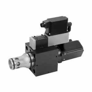
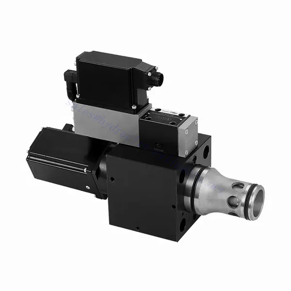
The WRCE series 2- and 3-way high-response flow hydraulic valve is a remarkable hydraulic component designed to deliver exceptional performance in fluid control applications. With its high-response flow capabilities, this valve revolutionizes hydraulic systems by providing precise and efficient flow control.
The WRCE series 2- and 3-way high-response flow hydraulic valve sets new standards in flow control precision and efficiency. With its high-response flow capabilities, compact design, and versatility, this valve empowers hydraulic systems to achieve optimal performance and energy efficiency. By following the recommended usage methods and maintenance guidelines, you can harness the full potential of the WRCE series valve and experience enhanced control and productivity in your hydraulic applications. Upgrade your hydraulic system today and unlock the advantages of efficiency and precision with the WRCE series 2- and 3-way high-response flow hydraulic valve.
WRCE Series 2-and 3-way High-response Flow Hydraulic Valve Key Characteristics:
- High-Response Flow:
- The WRCE series valve is engineered to offer high-response flow control, ensuring rapid and accurate adjustments to fluid flow rates.
- This characteristic enables precise control over hydraulic actuators, resulting in enhanced system performance, reduced energy consumption, and improved overall efficiency.
- Versatile 2- and 3-Way Configuration:
- This valve is available in both 2-way and 3-way configurations, providing flexibility to meet various hydraulic system requirements.
- The 2-way configuration allows for simple on/off control, while the 3-way design enables directional control, making it ideal for applications such as actuator extension and retraction.
- 컴팩트한 디자인:
- The WRCE series valve features a compact design, making it suitable for installations where space is limited.
- This compact size allows easy integration into various hydraulic systems without compromising performance or functionality.
- High-Pressure Rating:
- This valve is built to withstand high-pressure environments, ensuring reliable operation even in demanding hydraulic applications.
- Its robust construction and high-pressure rating make it suitable for use in systems that require efficient flow control under extreme operating conditions.
WRCE Series 2-and 3-way High-response Flow Hydraulic Valve Parameter:
| 일반적인 | |||||
| NS NG | 32 | 40 | 50 | ||
| 무게 | 킬로그램 | 11.2 | 17.3 | 24.6 | |
| Weight with shut-off valve …../…WK or …/…WL… | 킬로그램 | 12.5 | 18.6 | 25.9 | |
| Size of the pilot control valve (pilot) | NG | 6 | 6 | 6 | |
| 설치 위치 | Any, preferably horizontal | ||||
| 보관 온도 범위 | ℃ | –20 to +80 | |||
| 상황 온도 범위 | ℃ | –20 to +50 | |||
| Hydraulic (measured with HLP32, ϑoil=40℃ ±5℃) | |||||
| 최대 작동 압력 | – Main stagePort A、B | 술집 | NS 32~40: 350,NS 50: 420 | ||
| – Pilot control valve port X | 315 | ||||
| – Pilot control valve port Y | 210 | ||||
| Rated flow Δp=5bar | – Specifications …S…L (linear) | 리터/분 | 800 | 1200 | 2000 |
| – Specifications …S…R (linear with progressive fine control range) | 600 | 850 | 1400 | ||
| Nominal flow of pilot valve at Δp=70bar | 리터/분 | 12 | 40 | 40 | |
| Leakage of pilot valve at P=100bar | 리터/분 | 0.3 | 0.7 | 0.7 | |
| 유압유 | Mineral oil (HL,HLP) to DIN 51524 | ||||
| Hydraulic fluid temperature range | ℃ | 20 to +80;preferably +40 to +50 | |||
| 점도 범위 | mm2/에스 | 20 to 380;preferably 30 to 45 | |||
| Maximum admissible degree of contamination of the hydraulic fluid, cleanliness class according to ISO 4406 (c) | Class 20/18/15 | ||||
| 히스테리시스 | % | ≤ 0.2 | |||
| 히스테리시스 | % | ≤ 0.1 | |||
| 반응 민감도 | % | ≤ 0.1 | |||
| Response Time(step signa 0 ~ 100%) | 미시시피 | ≤ 20 | |||
| 전기 데이터 | |||||
| 전압 유형 | Direct voltage | ||||
| Type of signal | Analog | ||||
| Opening point calibration | % | ≦ 1 | |||
| Zero shift upon change of: | – Hydraulic fluid temperature | %/10K | ≦ 0.3 | ≦ 0.3 | ≦ 0.3 |
| – Pilot pressure in X | %/100bar | ≦ 0.7 | ≦ 0.7 | ≦ 0.7 | |
| – Return flow pressure in Y | %/bar | ≦ 0.3 | ≦ 0.3 | ≦ 0.3 | |
| The protection class of the valve according to EN60529 | IP65 with a mating connector mounted and locked | ||||
WRCE Series 2-and 3-way High-response Flow Hydraulic Valve Advantages:
• Pilot-operated two-stage cartridge high-frequency response throttle valve
• Suitable for closed-loop control of position, pressure, force and speed
• Pilot control valve: six-port direct-acting high-frequency response proportional valve with electric feedback
• Main stage: closed loop position control
• Integrated open loop and closed loop control electronics (OBE)
Usage Method Of WRCE Series 2-and 3-way High-response Flow Hydraulic Valve :
- 시스템 평가:
- Evaluate your hydraulic system and determine the specific flow control requirements.
- Identify whether the WRCE series valve is compatible with your system based on factors such as flow rates, pressure ratings, and the desired control functions.
- 밸브 선택:
- Select the appropriate variant of the WRCE series valve based on your system parameters and flow control needs.
- Consider factors such as flow capacity, pressure rating, response time, and compatibility with your specific application.
- 설치:
- Follow the manufacturer’s installation instructions carefully to ensure proper alignment and secure mounting of the valve.
- Make sure to create leak-free connections by using suitable hydraulic fittings, adapters, and seals. Tighten the connections adequately to prevent any fluid leaks.
- Control Signal Integration:
- Connect the control signal lines of the valve to a suitable control device, such as a hydraulic control module, electronic control unit, or manual control lever.
- Ensure proper wiring and compatibility between the valve and control device to achieve accurate and responsive flow control.
How To Hook Up Hydraulic Control Valve?
To hook up a hydraulic control valve, follow these steps:
- 밸브 유형 식별: Determine the specific type of hydraulic control valve you are working with, such as a directional control valve, pressure control valve, or flow control valve. Ensure that the valve is suitable for your application and compatible with your hydraulic system.
- 필요한 도구와 재료를 모으세요: Collect the necessary tools and materials, including appropriate hydraulic fittings, adapters, hoses, and wrenches. Refer to the manufacturer’s instructions for any specific tools or components needed.
- 유압 시스템 준비: 유압 시스템을 정지하고 릴리프 밸브를 작동하거나 유압 실린더를 수축시켜 압력을 해제하십시오. 이 단계는 안전에 매우 중요하며, 우발적인 움직임이나 유압유 누출을 방지합니다.
- 흐름 방향 식별: 유압 시스템의 흐름 방향을 확인하세요. 일반적으로 흐름 방향은 유압 부품에 화살표로 표시됩니다. 진행하기 전에 올바른 흐름 방향을 이해했는지 확인하세요.
- 설치 지점 찾기: Identify the optimal location to install the hydraulic control valve in your hydraulic system. Consider factors such as accessibility, proximity to the actuator or hydraulic component, and ease of operation. Ensure there is enough space for the valve to be mounted securely.
- 밸브 장착: Securely mount the hydraulic control valve in the chosen location using appropriate brackets or clamps. Ensure the valve is positioned correctly, aligning the inlet and outlet ports with the flow direction. Follow the manufacturer’s instructions for the specific mounting requirements of your valve.
- 입구 및 출구 포트를 연결합니다. Attach hydraulic hoses or tubing to the inlet and outlet ports of the hydraulic control valve. Use suitable hydraulic fittings and adapters to create a leak-free connection. Tighten the connections using wrenches to ensure a secure fit, but avoid over-tightening.
- Connect Control Lines: If your hydraulic control valve requires external control signals, connect the control lines from the control device, such as a joystick, lever, or solenoid, to the appropriate ports on the valve. Follow the manufacturer’s instructions for the correct wiring or connection configuration.
- 시스템 테스트: Once the hydraulic control valve is installed, slowly restore hydraulic system pressure. Test the system to ensure that the valve is functioning correctly. Operate the control device and observe the response of the hydraulic components to verify that the valve is controlling the flow, pressure, or direction as intended.
- Fine-tune and Adjust: Make any necessary adjustments to the hydraulic control valve to achieve the desired flow, pressure, or direction control. Refer to the manufacturer’s instructions for specific adjustment procedures. Regularly monitor the system for any leaks, pressure inconsistencies, or abnormal behavior.
공장의 역량 및 용량:
(1) 조립
당사는 최고 수준의 독자적인 연구개발 조립 플랫폼을 보유하고 있습니다. 유압 실린더 생산 작업장은 4개의 반자동 리프팅 실린더 조립 라인과 1개의 자동 틸트 실린더 조립 라인을 갖추고 있으며, 연간 100만 개의 설계 생산 능력을 갖추고 있습니다. 특수 실린더 작업장은 다양한 사양의 반자동 세척 조립 시스템을 갖추고 있으며, 연간 20만 개의 설계 생산 능력을 갖추고 있습니다. 또한, 유명 CNC 가공 장비, 머시닝 센터, 고정밀 실린더 가공 특수 장비, 로봇 용접기, 자동 세척기, 자동 실린더 조립기, 자동 도장 생산 라인을 갖추고 있습니다. 300대 이상의 핵심 장비를 보유하고 있으며, 장비 자원의 최적 배치 및 효율적인 사용을 통해 제품의 정밀성 요구 사항을 충족하고 고품질 요구를 충족합니다.


(2) 가공
가공공장은 맞춤형 경사레일 터닝센터, 가공센터, 고속 호닝머신, 용접로봇 및 기타 관련 장비를 갖추고 있으며, 최대 내경 400mm, 최대 길이 6m의 원통형 튜브를 가공할 수 있습니다.

(3) 용접

(4) 도장 및 코팅
소형, 중형 실린더 자동 수성 페인트 코팅 라인을 통해 자동 로봇 로딩 및 언로딩과 자동 분무를 실현하며, 교대당 4000개의 설계 용량을 달성합니다.
또한, 우리는 60개의 케이스를 교대로 생산할 수 있는 설계 용량을 갖춘 파워 체인으로 구동되는 대형 실린더용 반자동 페인트 생산 라인을 보유하고 있습니다.


(5) 테스트
당사는 실린더의 성능이 요구 사항을 충족하는지 확인하기 위해 일류 검사 시설과 테스트 베드를 갖추고 있습니다.

저희는 최고의 유압 실린더 제조업체 중 하나입니다. 다양한 유압 실린더를 공급할 수 있으며, 관련 제품도 제공합니다. 농업용 기어박스저희는 전 세계 고객에게 제품을 수출해 왔으며, 탁월한 제품 품질과 애프터서비스를 통해 좋은 평판을 얻고 있습니다. 국내외 고객 여러분의 사업 상담, 정보 교환, 그리고 우리와 협력하다!


