WMM Series Directional Hydraulic Valve With Mechanical, Manual Operation
WMM Series Directional Hydraulic Valve With Mechanical, Manual Operation
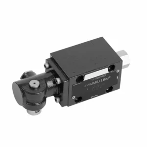
The WMM series directional hydraulic valve with mechanical, manual operation is a versatile and reliable solution designed to control hydraulic systems precisely. This hydraulic valve offers enhanced efficiency and flexibility with its advanced features and robust construction.
The WMM series directional hydraulic valve with mechanical, manual operation is a reliable and versatile solution for hydraulic systems. Its automatic manual operation and precise directional control offer enhanced flexibility and control for various applications. Following the recommended usage methods and adhering to regular maintenance practices, the WMM series hydraulic valve will continue providing efficient and reliable operation. Upgrade your hydraulic system with the WMM series directional valve and experience the benefits of enhanced control and versatility.
WMM Series Directional Hydraulic Valve With Mechanical, Manual Operation Key Characteristics:
- 기계식, 수동 작동:
- The WMM series hydraulic valve features a mechanical, manual operation, allowing operators to control the valve position manually.
- 이는 수동 조작이 필요하거나 요구되는 애플리케이션에서 유연성과 제어 기능을 제공합니다.
- 방향 제어:
- 이 유압 밸브는 유압 시스템 내에서 유체 흐름 방향을 정밀하게 제어할 수 있도록 해줍니다.
- 이를 통해 작업자는 원하는 흐름 경로를 선택할 수 있으므로 효율적이고 안정적인 작동이 보장됩니다.
- 내구성 있는 구조:
- The WMM series hydraulic valve is constructed with high-quality materials, ensuring durability and longevity.
- 견고한 설계로 까다로운 작동 환경에서도 견딜 수 있으며 안정적인 성능을 제공합니다.
- 컴팩트한 사이즈:
- The valve’s compact size allows easy integration into hydraulic systems with limited space.
- It is ideal for applications where space is a constraint without compromising performance.
WMM Series Directional Hydraulic Valve With Mechanical, Manual Operation Parameter:
NG6
| 유체 온도 범위 | ℃ | -30 ~ +80 (NBR 씰) | |
| -20 ~ +80(FKM 씰) | |||
| 포트 최대 작동 압력 | 포트 ABP | 술집 | 315 |
| 포트 T | 술집 | 160 | |
| 최대 유량 | 리터/분 | 60 | |
| Flowarea (switching neutral position) | Q 타입 | mm2 | 기호 Q의 경우, 공칭 단면적은 6%입니다. |
| W형 | mm2 | 기호 W의 경우, 공칭 단면적은 3%입니다. | |
| 체액 | 미네랄 오일; 인산 에스테르 | ||
| 점도 범위 | mm2/에스 | 2.8에서 500까지 | |
| 오염 정도 | 최대 허용 유체 오염도: Class 9. NAS 1638 또는 20/18/15, ISO4406 | ||
| 무게 | 킬로그램 | 1.6 | |
NG10
| 유체 온도 범위 | ℃ | -30 ~ +80 (NBR 씰) | |
| -20 ~ +80(FKM 씰) | |||
| 포트 최대 작동 압력 | 포트 ABP | 술집 | 315 |
| 포트 T | 술집 | 160 | |
| 최대 유량 | 리터/분 | 120 | |
| 유동 단면 (스위치 중립 위치) | V형 | mm2 | 11(A/B → T);10.3(P → A/B) |
| W형 | mm2 | 2.5(A/B → T) | |
| Q 타입 | mm2 | 5.5(A/B → T) | |
| 체액 | 미네랄 오일; 인산 에스테르 | ||
| 점도 범위 | mm2/에스 | 2.8에서 500까지 | |
| 오염 정도 | 최대 허용 유체 오염도: Class 9. NAS 1638 또는 20/18/15, ISO4406 | ||
| 무게 | 킬로그램 | 4.4 | |
NG16-32
| NS | 16 | 25 | 32 |
| 무게 | about 8 | about 12.2 | about 49 |
| Actuation force with detent N | about 75 | about 105 | about 170 |
| with spring return N | |||
| Actuation angle about the neutral position | 2*26° | 2*32° | 2*30° |
| Max. operating pressure Port A,B,P bar | 315 | ||
| Port T bar | 250 | ||
| 체액 | NBR 및 FKM 씰에 적합한 미네랄 오일 | ||
| Phosphate ester – for FKM seal | |||
| 유체 온도 범위 | -30 to +80(NBR seal) | ||
| -20 ~ +80(FKM 씰) | |||
| Viscosity range mm2/에스 | 2.8 to 380 | ||
| 오염 정도 | 최대 허용 유체 오염도: Class 9. NAS 1638 또는 20/18/15, ISO4406 | ||
WMM Series Directional Hydraulic Valve With Mechanical, Manual Operation Advantages:
• 직접 작동식 방향 슬라이드 밸브
• Sub-plate mounting
• Handle control
• Installation face follow DIN 24340 A, ISO 4401
Usage Method Of WMM Series Directional Hydraulic Valve With Mechanical, Manual Operation:
- 시스템 통합:
- Identify the appropriate location for the WMM series hydraulic valve within the hydraulic system, considering the desired flow direction and control requirements.
- 시스템의 압력 및 흐름 사양과의 호환성을 보장합니다.
- 적절한 브래킷이나 장착 액세서리를 사용하여 밸브를 단단히 고정하십시오.
- 유체 연결:
- 안전하고 누출 없는 연결을 위해 호환 가능한 유압 피팅과 호스를 선택하세요.
- 설치 과정에서 적절한 토크 값에 대한 제조업체의 지침을 따르세요.
- 안정적인 밀봉을 위해 적절한 나사산 밀봉제나 테이프를 사용하세요.
- 수동 조작:
- Familiarize yourself with the manual operation mechanism of the valve, including the lever or knob used to control the hydraulic valve position.
- 작업자가 밸브 위치를 수동으로 조정하는 올바른 절차를 이해하고 있는지 확인하십시오.
- 시스템 교정:
- Calibrate the hydraulic valve position and movement according to the desired flow direction and control requirements.
- 원하는 유로를 확보하고 밸브가 제대로 작동하는지 확인하기 위해 수동으로 밸브를 조정하십시오.
How To Adjust Valves On A Hydraulic Roller Cam?
Adjusting valves on a hydraulic roller cam requires careful attention to detail and following the proper procedure. Here’s a step-by-step guide to help you adjust the valves correctly:
- 엔진을 준비하세요:
- Ensure the engine is turned off and cool to the touch before starting the adjustment process.
- Locate the valve covers and remove them to access the valve train components.
- 밸브 조정의 올바른 순서를 확인하십시오:
- 엔진 제조사의 사양서 또는 서비스 설명서를 참조하여 해당 엔진에 맞는 정확한 밸브 조정 순서를 확인하십시오.
- 상사점(TDC) 위치를 찾으십시오.
- Rotate the engine’s crankshaft in the normal direction of rotation until the number one piston reaches the top dead center position on its compression stroke.
- Use a timing mark on the harmonic balancer or flywheel and a timing pointer to identify the TDC position accurately.
- Adjusting Valve Lash:
- Begin with the first cylinder in the valve adjustment sequence.
- Loosen the lock nut on the rocker arm stud using an appropriate wrench or socket.
- Use a feeler gauge of the recommended thickness specified by the engine manufacturer to check the valve lash (clearance) between the rocker arm and the valve stem.
- Slide the feeler gauge between the rocker arm and the valve stem. You should feel slight resistance but still be able to move the gauge back and forth.
- Adjust the valve lash by either tightening or loosening the rocker arm stud until the proper clearance is achieved. Turning the stud clockwise decreases the clearance, while counterclockwise increases it.
- Once you’ve set the correct valve lash, hold the rocker arm stud in place and tighten the lock nut securely.
- 이 과정을 반복하세요:
- Move to the next cylinder in the valve adjustment sequence and repeat steps 4 and 5 until all the valves have been adjusted.
- 밸브 커버를 다시 설치하십시오:
- 모든 실린더의 밸브 조정을 완료했으면 밸브 커버를 다시 설치하고 오일 누출을 방지하기 위해 제대로 밀봉되었는지 확인하십시오.
- 다시 한번 확인하세요:
- After adjusting the valves, it’s a good practice to go through the entire valve adjustment sequence once more to confirm that all clearances are within the specified range.
공장의 역량 및 용량:
(1) 조립
당사는 최고 수준의 독자적인 연구개발 조립 플랫폼을 보유하고 있습니다. 유압 실린더 생산 작업장은 4개의 반자동 리프팅 실린더 조립 라인과 1개의 자동 틸트 실린더 조립 라인을 갖추고 있으며, 연간 100만 개의 설계 생산 능력을 갖추고 있습니다. 특수 실린더 작업장은 다양한 사양의 반자동 세척 조립 시스템을 갖추고 있으며, 연간 20만 개의 설계 생산 능력을 갖추고 있습니다. 또한, 유명 CNC 가공 장비, 머시닝 센터, 고정밀 실린더 가공 특수 장비, 로봇 용접기, 자동 세척기, 자동 실린더 조립기, 자동 도장 생산 라인을 갖추고 있습니다. 300대 이상의 핵심 장비를 보유하고 있으며, 장비 자원의 최적 배치 및 효율적인 사용을 통해 제품의 정밀성 요구 사항을 충족하고 고품질 요구를 충족합니다.


(2) 가공
가공공장은 맞춤형 경사레일 터닝센터, 가공센터, 고속 호닝머신, 용접로봇 및 기타 관련 장비를 갖추고 있으며, 최대 내경 400mm, 최대 길이 6m의 원통형 튜브를 가공할 수 있습니다.

(3) 용접

(4) 도장 및 코팅
소형, 중형 실린더 자동 수성 페인트 코팅 라인을 통해 자동 로봇 로딩 및 언로딩과 자동 분무를 실현하며, 교대당 4000개의 설계 용량을 달성합니다.
또한, 우리는 60개의 케이스를 교대로 생산할 수 있는 설계 용량을 갖춘 파워 체인으로 구동되는 대형 실린더용 반자동 페인트 생산 라인을 보유하고 있습니다.


(5) 테스트
당사는 실린더의 성능이 요구 사항을 충족하는지 확인하기 위해 일류 검사 시설과 테스트 베드를 갖추고 있습니다.

저희는 최고의 유압 실린더 제조업체 중 하나입니다. 다양한 유압 실린더를 공급할 수 있으며, 관련 제품도 제공합니다. 농업용 기어박스저희는 전 세계 고객에게 제품을 수출해 왔으며, 탁월한 제품 품질과 애프터서비스를 통해 좋은 평판을 얻고 있습니다. 국내외 고객 여러분의 사업 상담, 정보 교환, 그리고 우리와 협력하다!