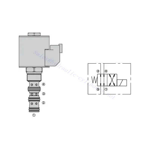
30SD10-40 Solenoid Directional Valve
Kā viens no hidraulisko cilindru ražotājiem, piegādātājiem un eksportētājiem, mēs piedāvājam hidrauliskos cilindrus un daudzus citus produktus.
Lūdzu, sazinieties ar mums, lai saņemtu sīkāku informāciju.
Pasts:sales@hydraulic-cylinders.net
Hidraulisko cilindru ražotājs, piegādātājs, eksportētājs.
30SD10-40 Solenoid Directional Valve
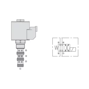
The 30SD10-40 solenoid directional valve is a high-performance industrial component designed to deliver precise and reliable fluid control in a variety of applications. With its advanced features, durable construction, and user-friendly design, this solenoid directional valve offers enhanced efficiency and operational reliability.
The 30SD10-40 solenoid directional valve is a reliable and versatile component that offers precise fluid control in industrial applications. Its robust construction, precision control, and reliable performance enhance efficiency and productivity in fluid control systems. By following the recommended usage methods and maintenance guidelines, you can ensure optimal performance and longevity of the 30SD10-40 solenoid directional valve in your industrial operations.
30SD10-40 Solenoid Directional Valve Characteristics:
- Robust Construction: The 30SD10-40 solenoid directional valve is built with exceptional craftsmanship and high-quality materials, ensuring durability and longevity. Its sturdy construction allows it to withstand demanding industrial environments, providing reliable performance even in harsh conditions.
- Versatile Functionality: This solenoid directional valve offers versatile functionality, making it suitable for a wide range of applications. It effectively controls the direction of fluid flow, enabling precise and efficient operation in various industrial systems.
- Precision Control: The 30SD10-40 solenoid directional valve provides exceptional precision in fluid control. It allows for accurate regulation and adjustment of fluid direction and pressure, ensuring optimal performance and efficiency in industrial processes.
- Reliable Performance: This solenoid directional valve delivers reliable performance, minimizing the risk of system failures or interruptions. It operates with dependability, contributing to increased productivity and reduced downtime in industrial operations.
30SD10-40 Solenoid Directional Valve Parameter:
| Nominālais spiediens | 207 bar(3000 psi) | |
| Maksimālā plūsma | 23 l/min (6 galoni minūtē) | |
| Šķidrums | Minerālu bāzes vai sintētiskas ar eļļošanas īpašībām | |
| Temperature range ℃ | -54 līdz 107 ℃ (poliuretāna blīvējumi) | |
| -40 līdz 100 ℃ (Buna N blīvējumi) | ||
| -26 līdz 204 ℃ (fluorogļūdeņraža blīvējumi) | ||
| Viskozitātes diapazons | 7,4 līdz 420 mm2/s | |
| Piesārņojuma pakāpe | The minimum pollution level is ISO4406 level 20/18/14, and level 17/15/13 is recommended to prolong the service life | |
| Iekšējā noplūde | ≤ 82 mL/min@207bar | |
| Dobums | VC10-4 | |
| Spoles slodzes vērtējums | Nepārtraukts nominālais spriegums no 85% līdz 115% | |
| Sākotnējā spoles strāvas patēriņš pie 20 ℃ | E-spole | 1,7 A pie 12 V līdzstrāvas; 0,85 A pie 24 V līdzstrāvas |
| D-spole | 1,67 A pie 12 V līdzstrāvas; 0,83 A pie 24 V līdzstrāvas | |
| Minimālais ievilkšanas spriegums | 85% no nominālā pie 207 bāriem | |
30SD10-40 Solenoid Directional Valve Advantages:
• Nepārtrauktas darbības spole
• Kārtridžus var savstarpēji aizvietot atkarībā no sprieguma
• Papildus pieejamas ūdensnecaurlaidīgas E-spoles ar aizsardzības pakāpi līdz IP69K
• Efektīva slapjā armatūras konstrukcija
• Nozares kopējā dobumā
• Rūdītas detaļas ilgam kalpošanas laikam
Usage Method Of 30SD10-40 Solenoid Directional Valve :
- Integration into the System: Integrate the 30SD10-40 Solenoid Directional Valve into the fluid control system following the manufacturer’s guidelines and specifications. Ensure proper alignment and connection between the valve and other system components to achieve optimal performance.
- Electrical Connection: Establish a secure electrical connection for the solenoid directional valve. Follow the provided wiring diagram and ensure correct polarity to prevent electrical malfunctions. Adhere to safety guidelines when working with electrical connections.
- Fluid Flow Direction Control: Utilize the solenoid directional valve to control the direction of fluid flow. The valve is typically equipped with a lever or actuator for manual adjustment. Alternatively, it can be integrated into an automated control system for remote operation.
- Pressure Adjustment: Use the solenoid directional valve to regulate fluid pressure within the system. Adjust the valve’s settings to achieve the desired pressure levels for optimal performance and efficiency.
How To Read Hydraulic Valve Schematics?
Reading hydraulic valve schematics requires a basic understanding of hydraulic symbols and their meanings. Here are the steps to help you read hydraulic valve schematics:
- Familiarize Yourself With Hydraulic Symbols: Hydraulic schematics use graphical symbols to represent various components and functions. Common symbols include squares for valves, lines for pipes or hoses, arrows for flow direction, and circles for pressure or flow control devices. Make sure you understand the meaning of these symbols before proceeding.
- Identify The Valve Types: Look for the valve symbols in the schematic. Valves can be represented by squares with different shapes and orientations. For example, a square with a diagonal line represents a check valve, while a square with an arrow inside denotes a directional control valve.
- Determine The Valve Function: Each valve symbol indicates its specific function. Directional control valves determine the flow direction of hydraulic fluid, while pressure control valves regulate pressure levels. Flow control valves manage the rate of fluid flow, and check valves allow flow in one direction only.
- Observe The Valve Connections: Pay attention to the lines or arrows entering and exiting the valve symbol. These lines represent the hydraulic fluid flow paths. Arrows indicate the flow direction, and lines connecting valves and other components indicate the connections.
- Analyze The Valve Ositions: Some hydraulic valve schematics include symbols to illustrate the valve positions. These symbols typically depict the valve spool or lever in different positions, such as open, closed, or partially open. Understanding the valve positions helps you determine the flow paths and the state of the hydraulic system.
- Consider Additional Symbols And Annotations: Hydraulic schematics may include additional symbols and annotations to indicate pressure gauges, flow meters, filters, accumulators, or other components. Familiarize yourself with these symbols and their meanings to gain a comprehensive understanding of the system.
- Follow The Flow Paths: Trace the flow paths from the hydraulic power source through the various valves and components to the actuator or desired output. Understand how the valves interact with one another and how they control fluid flow, pressure, and direction to achieve the desired system operation.
- Refer To The Legend Or Key: The schematic should have a legend or key that explains the meaning of each symbol used in the diagram. If you encounter unfamiliar symbols or have doubts about their meaning, refer to the legend for clarification.
- Seek Additional Resources If Needed: If you need a more in-depth understanding of hydraulic valve schematics, consider referring to hydraulic textbooks, online resources, or consulting with hydraulic experts who can provide guidance and explanations tailored to your specific needs.
Rūpnīcas iespējas un jauda:
(1) Montāža
Mums ir pirmklasīga neatkarīga pētniecības un attīstības montāžas platforma. Hidraulisko cilindru ražošanas darbnīcā ir četras pusautomātiskas pacelšanas cilindru montāžas līnijas un viena automātiskā slīpuma cilindru montāžas līnija ar projektēto gada ražošanas jaudu 1 miljons vienību. Speciālo cilindru darbnīca ir aprīkota ar dažādu specifikāciju pusautomātisku tīrīšanas montāžas sistēmu ar projektēto gada ražošanas jaudu 200 000 vienību un aprīkota ar slavenām CNC apstrādes iekārtām, apstrādes centru, augstas precizitātes cilindru apstrādes speciālo aprīkojumu, robotizētu metināšanas iekārtu, automātisku tīrīšanas iekārtu, automātisku cilindru montāžas iekārtu un automātisku krāsošanas ražošanas līniju. Esošais kritiskais aprīkojums ir vairāk nekā 300 komplektu (komplektu). Optimāla iekārtu resursu sadale un efektīva izmantošana nodrošina produktu precizitātes prasības un apmierina produktu augstās kvalitātes prasības.


(2) Apstrāde
Apstrādes cehs ir aprīkots ar pielāgotu slīpo sliežu virpošanas centru, apstrādes centru, ātrgaitas asināšanas mašīnu, metināšanas robotu un citu saistītu aprīkojumu, kas var apstrādāt cilindriskas caurules ar maksimālo iekšējo diametru 400 mm un maksimālo garumu 6 metri.

(3) Metināšana

(4) Krāsošana un pārklāšana
Ar mazām un vidēja izmēra cilindriskām automātiskām ūdens bāzes krāsu pārklāšanas līnijām, lai panāktu automātisku robotu iekraušanu un izkraušanu un automātisku izsmidzināšanu, projektētā jauda ir 4000 gabali maiņā;
Mums ir arī pusautomātiska krāsu ražošanas līnija lieliem baloniem, ko darbina ķēdes piedziņa, ar 60 kastu konstrukcijas jaudu vienā maiņā.


(5) Testēšana
Mums ir augstākās klases pārbaudes iekārtas un testēšanas stendi, lai nodrošinātu, ka balona veiktspēja atbilst prasībām.

Mēs esam viens no labākajiem hidraulisko cilindru ražotājiem. Mēs varam piedāvāt visaptverošus hidrauliskos cilindrus. Mēs nodrošinām arī atbilstošus lauksaimniecības pārnesumkārbas. Mēs esam eksportējuši savus produktus klientiem visā pasaulē un esam ieguvuši labu reputāciju, pateicoties mūsu izcilajai produktu kvalitātei un pēcpārdošanas servisam. Mēs aicinām klientus no valsts un ārvalstīm sazināties ar mums, lai risinātu biznesa sarunas, apmainītos ar informāciju un... sadarboties ar mums!
Hidrauliskā cilindra pielietojums:
