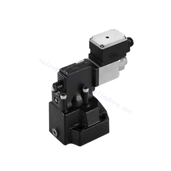
DRE(E) Series Proportional Pressure Reducing Hydraulic Valve
DRE(E) Series Proportional Pressure Reducing Hydraulic Valve
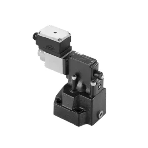
The DRE(E) series proportional pressure-reducing hydraulic valve is a cutting-edge hydraulic component that provides precise pressure control in hydraulic systems. With its advanced proportional control technology, this valve ensures optimal performance, efficiency, and safety.
The DRE(E) series proportional pressure-reducing hydraulic valve empowers hydraulic systems with precise pressure control, enhanced efficiency, and equipment protection. With its advanced proportional control technology, this valve ensures optimal performance across various applications. By following the recommended usage methods and maintenance guidelines, you can maximize the benefits and reliability of the DRE(E) series valve, elevating the pressure control and overall performance of your hydraulic system. Upgrade your hydraulic setup today and experience superior pressure regulation with the DRE(E) series proportional pressure-reducing hydraulic valve.
DRE(E) Series Proportional Pressure Reducing Hydraulic Valve Key Characteristics:
- Proportional Pressure Reduction:
- The DRE(E) series valve offers precise and proportional pressure reduction, enabling dynamic hydraulic pressure control.
- It ensures accurate pressure regulation, maintaining a consistent and safe pressure level within the hydraulic system.
- Forbedret systemeffektivitet:
- This valve enables precise hydraulic pressure control, resulting in enhanced system efficiency and reduced energy consumption.
- By maintaining the desired pressure levels, it minimizes pressure fluctuations, optimizes system performance, and lowers operational costs.
- Safety and Equipment Protection:
- The DRE(E) series valve acts as a protective mechanism by limiting the pressure within the hydraulic system, safeguarding equipment and operators.
- It prevents excessive pressure build-up, reducing the risk of component damage, system failures, and potential accidents.
- Proportional Control Functionality:
- With its proportional control technology, the DRE(E) series valve offers smooth and precise pressure adjustment.
- It allows for real-time pressure control, enabling seamless integration into various hydraulic systems and applications.
DRE(E) Series Proportional Pressure Reducing Hydraulic Valve Parameter:
| General | ||||
| Væske | Mineralolje egnet for NBR- og FKM-tetninger | |||
| Fosfatester for FKM-tetning | ||||
| Væsketemperaturområde | ℃ | -30 til +80 (NBR-tetninger) | ||
| -20 til +80 (FKM-tetninger) | ||||
| Viskositetsområde | mm2/s | 2.8 to 380 | ||
| Grad av forurensning | Maksimal tillatt grad av væskeforurensning: Klasse 9. NAS 1638 eller 20/18/15, ISO4406 | |||
| Maks. driftstrykk | 315 bar | |||
| Port A、B、X | bar | 50; 100; 200; 315 | ||
| Maks. innstillingstrykk | bar | In relation to Flow (Q), see characteristic curves | ||
| Min. innstillbart trykk | =Min. innstillbart trykk | |||
| Min. innstillbart trykk ved 0 kommandoverdi | Separate and at zero pressure to tanks | |||
| Return oil pressure port Y | bar | Innstilling av trykk | Pressure range under Max. safety pressure | |
| Max. pressure safety (infinitely adjustable) | 50 bar | 10-60+20 bar | ||
| 100 bar | 10-120+20 bar | |||
| 200 bar | 10-220+20 bar | |||
| 315 bar | 10-340+20 bar | |||
| Max. pressure safety setting condition | When rated pressure is 50 bar, between 60 bar and 80 bar | |||
| When rated pressure is 100 bar, between120 bar and 140 bar | ||||
| When rated pressure is 200 bar, between 220 bar and 240 bar | ||||
| When rated pressure is 315 bar, between 340 bar and 360 bar | ||||
| Størrelse | 10 | 25 | 32 | |
| Maks. strømningshastighet | 200 | 400 | 600 | |
| Pilot oil (for pilot valve)) | l/min | 0.7 to 2 | ||
| Linearitet | l/min | ±3.5% | ||
| Repeterbarhet | <±2% | |||
| Hysterese | with shimmy | without shimmy | ||
| ±1.5% P max (200Hz, amplitude 200mAsss) | ±4.5% P max | |||
| Byttetid | 30~150ms(independent with the system) | |||
| Elektriske data | ||||
| Power | DC | |||
| Min. solenoid current | mA | 100 | ||
| Max. solenoid current | mA | 800 | ||
| Spolemotstand | 19.5Ω at 20℃, Max. warm value: 28.8Ω | |||
| Working status | Continuous | |||
| Max. Ambient temperature range | +50℃ | |||
| Elektrisk tilkobling | Plug-in connector to DIN 43 650/2 +SL/PG11 | |||
| Insulation to DIN 40 050 | IP65 | |||
| Amplifier | VT2000 | |||
DRE(E) Series Proportional Pressure Reducing Hydraulic Valve Advantages:
• Brukes for montering av bunnplate
• Installation face follow DIN24340 E and ISO 6264
• Brukes i installasjon av oljebaneblokk
• Fire trykkområder
• Highest pressure protection structure (optional)
• Matching electronic amplifier VT-2000 type (must be ordered separately)
Usage Method Of DRE(E) Series Proportional Pressure Reducing Hydraulic Valve:
- Systemevaluering:
- Evaluer det hydrauliske systemet ditt og identifiser de spesifikke kravene til trykkontroll.
- Determine if the DRE(E) series valve is compatible with your system based on its pressure range, flow capacity, and other specifications.
- Ventilvalg:
- Choose the appropriate DRE(E) series valve variant based on your system parameters, pressure range, and flow requirements.
- Consider maximum pressure rating, response time, and operational conditions.
- Installasjon:
- Følg produsentens installasjonsinstruksjoner nøye, og sørg for riktig justering og sikker montering av ventilen.
- Koble ventilen til det hydrauliske systemet. Sørg for lekkasjefrie tilkoblinger og riktig justering av strømningsretningen.
- Trykkjustering:
- Utilize the proportional control signal or adjustment mechanism provided with the DRE(E) series valve to set the desired pressure reduction level.
- Adjust the valve incrementally, monitoring the pressure gauge readings and system response to achieve precise pressure control.
How To Adjust Hydraulic Pressure Relief Valve?
Adjusting a hydraulic pressure relief valve allows you to regulate the maximum pressure within a hydraulic system. This is important for maintaining system integrity and preventing damage to components. Here’s a step-by-step guide on how to adjust a hydraulic pressure relief valve:
- Identify the Pressure Relief Valve:
- Locate the hydraulic pressure relief valve in your system. It is typically positioned in the hydraulic line or integrated into a manifold block.
- Understand the Valve Design:
- Familiarize yourself with the specific design of the pressure relief valve you are working with. Different valves may have varying adjustment mechanisms, such as a knob, screw, or locknut.
- Determine the Desired Pressure Setting:
- Assess the requirements of your hydraulic system and determine the desired maximum pressure. Consider the system’s specifications, load conditions, and safety limits.
- Klargjør systemet:
- Before making any adjustments, shut off the hydraulic system and relieve the pressure by moving the control levers back and forth or following the manufacturer’s recommended procedure.
- Locate the Adjustment Mechanism:
- Identify the adjustment mechanism on the pressure relief valve. It could be a knob, screw, or locknut positioned on the valve body or adjacent to it.
- Adjust the Valve:
- If the valve has a knob or handle, turn it clockwise to increase the pressure relief setting or counterclockwise to decrease it. If the valve has a screw, turn it clockwise to increase the ground or counterclockwise to drop it.
- Make Incremental Adjustments:
- When adjusting the pressure relief valve, make small, incremental changes to avoid sudden or drastic variations in pressure. This allows you to fine-tune the system and prevent potential damage.
- Observe the System:
- With each adjustment, observe the hydraulic system’s pressure gauge or indicator to see the effect of the changes. Ensure that the pressure stays within the desired range.
- Test og verifiser:
- Gradually increase the system’s pressure and monitor the pressure relief valve’s response. Ensure it relieves stress when the maximum set pressure is reached and maintains the desired maximum pressure.
- Lock the Adjustment:
- Once you have achieved the desired pressure setting, secure the adjustment mechanism to prevent unintended changes. Some valves may have a locking nut or set screw that can be tightened to hold the adjustment in place.
- Document the Adjustment:
- Keep a record of the adjusted pressure relief setting for future reference and maintenance purposes. This documentation will help maintain consistency and aid troubleshooting efforts.
Fabrikkens kapasitet og kapasitet:
(1) Montering
Vi har en førsteklasses uavhengig forsknings- og utviklingsplattform for montering. Verkstedet for produksjon av hydrauliske sylindere har fire halvautomatiske monteringslinjer for løftesylindere og én automatisk monteringslinje for vippesylindere, med en årlig produksjonskapasitet på 1 million enheter. Spesialsylinderverkstedet er utstyrt med ulike spesifikasjoner for et halvautomatisk rengjøringsmonteringssystem med en årlig produksjonskapasitet på 200 000 enheter, og er utstyrt med kjent CNC-maskineringsutstyr, et maskineringssenter, spesialutstyr for høypresisjons sylinderbehandling, en robotsveisemaskin, en automatisk rengjøringsmaskin, en automatisk sylindermonteringsmaskin og en automatisk produksjonslinje for lakkering. Vi har mer enn 300 sett (sett) av kritisk utstyr. Optimal allokering og effektiv bruk av utstyrsressurser sikrer nøyaktighetskravene til produktene og oppfyller produktenes høye kvalitetsbehov.


(2) Maskinering
Maskineringsverkstedet er utstyrt med et spesialtilpasset dreiesenter for skrå skinner, maskineringssenter, høyhastighets honemaskin, sveiserobot og annet relatert utstyr, som kan håndtere bearbeiding av sylinderrør med en maksimal indre diameter på 400 mm og en maksimal lengde på 6 meter.

(3) Sveising

(4) Maling og belegg
Med små og mellomstore sylinderautomatiske vannbaserte malingsbeleggslinjer, for å oppnå automatisk robotlasting og -lossing og automatisk sprøyting, er den designede kapasiteten 4000 stykker per skift;
Vi har også en halvautomatisk produksjonslinje for maling for store sylindere drevet av en kabelkjede, med en designkapasitet på 60 kasser per skift.


(5) Testing
Vi har førsteklasses inspeksjonsfasiliteter og testbenker for å sikre at sylinderens ytelse oppfyller kravene.

Vi er en av de beste produsentene av hydrauliske sylindere. Vi kan tilby et omfattende utvalg av hydrauliske sylindere. Vi tilbyr også tilsvarende landbruksgirkasserVi har eksportert produktene våre til kunder over hele verden og opparbeidet oss et godt rykte på grunn av vår overlegne produktkvalitet og ettersalgsservice. Vi ønsker kunder i inn- og utland velkommen til å kontakte oss for å forhandle om forretninger, utveksle informasjon og samarbeide med oss!