30SD10-40 Solenoid Directional Valve
Fiind unul dintre producătorii, furnizorii și exportatorii de cilindri hidraulici, oferim cilindri hidraulici și multe alte produse.
Vă rugăm să luați legătura cu noi pentru detalii.
Mail:sales@hydraulic-cylinders.net
Producător, furnizor, exportator de cilindri hidraulici.
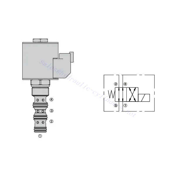
30SD10-40 Solenoid Directional Valve
The 30SD10-40 solenoid directional valve is a high-performance industrial component designed to deliver precise and reliable fluid control in a variety of applications. With its advanced features, durable construction, and user-friendly design, this solenoid directional valve offers enhanced efficiency and operational reliability.
The 30SD10-40 solenoid directional valve is a reliable and versatile component that offers precise fluid control in industrial applications. Its robust construction, precision control, and reliable performance enhance efficiency and productivity in fluid control systems. By following the recommended usage methods and maintenance guidelines, you can ensure optimal performance and longevity of the 30SD10-40 solenoid directional valve in your industrial operations.
30SD10-40 Solenoid Directional Valve Characteristics:
- Robust Construction: The 30SD10-40 solenoid directional valve is built with exceptional craftsmanship and high-quality materials, ensuring durability and longevity. Its sturdy construction allows it to withstand demanding industrial environments, providing reliable performance even in harsh conditions.
- Versatile Functionality: This solenoid directional valve offers versatile functionality, making it suitable for a wide range of applications. It effectively controls the direction of fluid flow, enabling precise and efficient operation in various industrial systems.
- Precision Control: The 30SD10-40 solenoid directional valve provides exceptional precision in fluid control. It allows for accurate regulation and adjustment of fluid direction and pressure, ensuring optimal performance and efficiency in industrial processes.
- Reliable Performance: This solenoid directional valve delivers reliable performance, minimizing the risk of system failures or interruptions. It operates with dependability, contributing to increased productivity and reduced downtime in industrial operations.
30SD10-40 Solenoid Directional Valve Parameter:
| Rated pressure | 207 bar(3000 psi) | |
| Peak flow | 23 L/min (6 gpm) | |
| Fluid | Mineral-based or synthetics with lubricating properties | |
| Temperature range ℃ | -54 to 107 ℃ (Polyurethane seals) | |
| -40 to 100 ℃ (Buna N seals) | ||
| -26 to 204 ℃ (Fluorocarbon seals) | ||
| Viscosity range | 7.4 to 420 mm2/s | |
| Degree of contamination | The minimum pollution level is ISO4406 level 20/18/14, and level 17/15/13 is recommended to prolong the service life | |
| Internal Leakage | ≤ 82 mL/min@207bar | |
| Cavity | VC10-4 | |
| Coil Duty Rating | Continuous from 85% to 115% of nominal voltage | |
| Initial Coil Current Draw at 20℃ | E-coil | 1.7A at 12VDC; 0.85A at 24VDC |
| D-coil | 1.67A at 12VDC; 0.83A at 24VDC | |
| Minimum pull-in voltage | 85% of nominal at 207 bar | |
30SD10-40 Solenoid Directional Valve Advantages:
• Continuous-duty rated coil
• Cartridges are voltage interchangeable
• Optional waterproof E-Coils rated up to IP69K
• Efficient wet-armature construction
• Industry common cavity
• Hardened parts for long life
Usage Method Of 30SD10-40 Solenoid Directional Valve :
- Integration into the System: Integrate the 30SD10-40 Solenoid Directional Valve into the fluid control system following the manufacturer’s guidelines and specifications. Ensure proper alignment and connection between the valve and other system components to achieve optimal performance.
- Electrical Connection: Establish a secure electrical connection for the solenoid directional valve. Follow the provided wiring diagram and ensure correct polarity to prevent electrical malfunctions. Adhere to safety guidelines when working with electrical connections.
- Fluid Flow Direction Control: Utilize the solenoid directional valve to control the direction of fluid flow. The valve is typically equipped with a lever or actuator for manual adjustment. Alternatively, it can be integrated into an automated control system for remote operation.
- Pressure Adjustment: Use the solenoid directional valve to regulate fluid pressure within the system. Adjust the valve’s settings to achieve the desired pressure levels for optimal performance and efficiency.
How To Read Hydraulic Valve Schematics?
Reading hydraulic valve schematics requires a basic understanding of hydraulic symbols and their meanings. Here are the steps to help you read hydraulic valve schematics:
- Familiarize Yourself With Hydraulic Symbols: Hydraulic schematics use graphical symbols to represent various components and functions. Common symbols include squares for valves, lines for pipes or hoses, arrows for flow direction, and circles for pressure or flow control devices. Make sure you understand the meaning of these symbols before proceeding.
- Identify The Valve Types: Look for the valve symbols in the schematic. Valves can be represented by squares with different shapes and orientations. For example, a square with a diagonal line represents a check valve, while a square with an arrow inside denotes a directional control valve.
- Determine The Valve Function: Each valve symbol indicates its specific function. Directional control valves determine the flow direction of hydraulic fluid, while pressure control valves regulate pressure levels. Flow control valves manage the rate of fluid flow, and check valves allow flow in one direction only.
- Observe The Valve Connections: Pay attention to the lines or arrows entering and exiting the valve symbol. These lines represent the hydraulic fluid flow paths. Arrows indicate the flow direction, and lines connecting valves and other components indicate the connections.
- Analyze The Valve Ositions: Some hydraulic valve schematics include symbols to illustrate the valve positions. These symbols typically depict the valve spool or lever in different positions, such as open, closed, or partially open. Understanding the valve positions helps you determine the flow paths and the state of the hydraulic system.
- Consider Additional Symbols And Annotations: Hydraulic schematics may include additional symbols and annotations to indicate pressure gauges, flow meters, filters, accumulators, or other components. Familiarize yourself with these symbols and their meanings to gain a comprehensive understanding of the system.
- Follow The Flow Paths: Trace the flow paths from the hydraulic power source through the various valves and components to the actuator or desired output. Understand how the valves interact with one another and how they control fluid flow, pressure, and direction to achieve the desired system operation.
- Refer To The Legend Or Key: The schematic should have a legend or key that explains the meaning of each symbol used in the diagram. If you encounter unfamiliar symbols or have doubts about their meaning, refer to the legend for clarification.
- Seek Additional Resources If Needed: If you need a more in-depth understanding of hydraulic valve schematics, consider referring to hydraulic textbooks, online resources, or consulting with hydraulic experts who can provide guidance and explanations tailored to your specific needs.
Capabilitatea și capacitatea fabricii:
(1) Montaj
Avem o platformă de asamblare independentă de cercetare și dezvoltare de primă clasă. Atelierul de producție a cilindrilor hidraulici are patru linii de asamblare semiautomate pentru cilindri de ridicare și o linie de asamblare automată a cilindrilor de înclinare, cu o capacitate de producție anuală proiectată de 1 milion de bucăți. Atelierul de cilindri speciali este echipat cu diverse specificații ale unui sistem de asamblare semi-automat de curățare, cu o capacitate de producție anuală proiectată de 200.000 și dotat cu echipamente celebre de prelucrare CNC, un centru de prelucrare, un echipament special de prelucrare a cilindrilor de înaltă precizie, o mașină de sudură robotizată, o mașină de curățare automată, o mașină de asamblare automată a cilindrilor și o linie de producție automată de vopsire. Echipamente critice existente de peste 300 de seturi (seturi). Alocarea optimă și utilizarea eficientă a resurselor de echipamente asigură cerințele de precizie ale produselor și satisface nevoile de înaltă calitate ale produselor.


(2) Prelucrare
Atelierul de prelucrare este echipat cu un centru de strunjire cu șină înclinată personalizat, un centru de prelucrare, o mașină de honuire de mare viteză, un robot de sudură și alte echipamente conexe, care pot gestiona prelucrarea tuburilor cilindrice cu un diametru interior maxim de 400 mm și o lungime maximă de 6 metri.

(3) Sudură

(4) Vopsire și acoperire
Cu linii automate de acoperire cu vopsea pe bază de apă cu cilindru de dimensiuni mici și medii, pentru a realiza încărcarea și descărcarea automată a robotului și pulverizarea automată, capacitatea de proiectare de 4000 de bucăți pe schimb;
Avem, de asemenea, o linie de producție semi-automată de vopsire pentru cilindri mari, acționată de un lanț de putere, cu o capacitate de proiectare de 60 de cutii pe schimb.


(5) Testarea
Dispunem de instalații de inspecție și bancuri de testare de primă clasă pentru a ne asigura că performanța cilindrului îndeplinește cerințele.

We are one of the best hydraulic cylinder manufacturers. We can offer comprehensive hydraulic cylinders. We also provide corresponding cutii de viteze agricole. We have exported our products to clients worldwide and earned a good reputation because of our superior product quality and after-sales service. We welcome customers at home and abroad to contact us to negotiate business, exchange information, and să coopereze cu noi!
Faceți un tur al fabricii noastre VR:
Faceți un tur al fabricii noastre VR cu următoarele
Cilindru hidraulic Aplicație:
