WEH Series Directional Hydraulic Valves Of Pilot Operated
WEH Series Directional Hydraulic Valves Of Pilot Operated
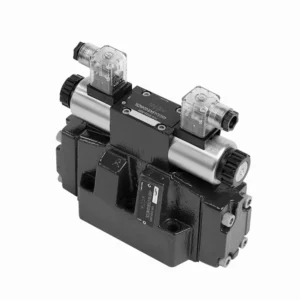
The WEH series directional hydraulic valves of pilot operated are advanced components that provide precise and efficient control over hydraulic systems. Designed to meet the demands of various industries, these valves offer exceptional performance, reliability, and versatility.
The WEH series directional hydraulic valves of pilot operated are reliable, high-performance components that empower operators with precise control and efficient fluid management in hydraulic systems. With their pilot-operated design, exceptional directional control, a wide range of configurations, and high flow capacity, these valves offer the reliability and versatility required in various industries. Following the recommended usage methods and adhering to regular maintenance practices, the WEH series valves will continue delivering exceptional performance. Upgrade your hydraulic system with the WEH series directional hydraulic valves operated and experience the benefits of precision, control, and reliability.
WEH Series Directional Hydraulic Valves Of Pilot Operated Key Characteristics:
- Конструкция, управляемая пилотом:
- The WEH series valves utilize a pilot-operated design, which enhances their responsiveness and control accuracy.
- This design enables the valves to handle high-pressure applications, ensuring optimal performance easily.
- Направленное управление:
- These hydraulic valves excel in providing precise directional control of hydraulic fluid.
- Операторы могут легко управлять потоком жидкости и направлять его к различным приводам или компонентам гидравлической системы.
- Wide Range of Configurations:
- The WEH series valves are available in various configurations, including various sizes, flow rates, and pressure ratings.
- This versatility allows them to be tailored to specific application requirements and system specifications.
- Высокая пропускная способность:
- These valves are designed to handle high flow rates, making them suitable for applications that demand substantial fluid flow.
- Оптимизированные внутренние каналы и прочная конструкция обеспечивают минимальное падение давления и эффективное управление жидкостью.
WEH Series Directional Hydraulic Valves Of Pilot Operated Parameter:
НГ10
| Технические характеристики | WEH10 type | |||||||||
| Max. operating pressure:P、A、B | 350 | |||||||||
| Порт Т | With external pilot oil drain bar | 315 | ||||||||
| With internal pilot oil drain bar | DC 210 AC 160 | |||||||||
| Порт Y | With external pilot oil drain bar | DC 210 AC 160 | ||||||||
| Min. control pressure | With external pilot oil supply ( not apply to C、Z、 F、G、H、P、T、V) bar |
3-position valve 10 | ||||||||
| Spring-return 2-position valve 10 | ||||||||||
| Hydraulic-return 2-position valve 7 | ||||||||||
| With internal pilot oil supply ( apply to C、Z、F、 G、H、P、T、V) bar |
6.5 | |||||||||
| Max. control pressure bar | 250 | |||||||||
| Жидкость | Mineral oil,Phosphate ester | |||||||||
| Fluid temperature range ℃ | -30 to +80 ( NBR seals | |||||||||
| -20 to +80 ( FKM seals ) | ||||||||||
| Viscosity range mm2/с | 2,8–500 | |||||||||
| Switching pilot oil volume cm3 | 3-position valve 2.04 | |||||||||
| 2-position valve 4.08 | ||||||||||
| Switching times (= Valve switching time from the neutral position to the switched position)(AC and DC ) | ||||||||||
| Control pressure bar | 70 | 140 | 210 | 250 | ||||||
| AC | округ Колумбия | AC | округ Колумбия | AC | округ Колумбия | AC | округ Колумбия | |||
| 3-position valve ms | 30 | 65 | 25 | 60 | 20 | 55 | 15 | 50 | ||
| 2-position valve ms | 35 | 80 | 30 | 75 | 25 | 70 | 20 | 65 | ||
| Switching times (= Valve switching time from the switched position to the neutral position) | ||||||||||
| 3-position valve ms | 30 | |||||||||
| 2-position valve ms | 35 | 40 | 30 | 35 | 25 | 30 | 20 | 25 | ||
| Положение установки | HC、HD、HK、HZ、HY Type hydraulic-return valves are installed horizontally, the rest can be installed arbitrarily | |||||||||
| Flow of shortest switching time L/min | about 35 | |||||||||
| Масса | Single solenoid valve kg | 6.7 | ||||||||
| Double solenoid valve kg | 7.1 | |||||||||
| Switching time regulator kg | 1.0 | |||||||||
| Reducing valve kg | 0.5 | |||||||||
НГ16
| Технические характеристики | WEH16… type | |||||||||||||
| Max. operating pressure:P、A、B | 350 | |||||||||||||
| Порт Т | With external pilot oil drain bar | 250 | ||||||||||||
| With internal pilot oil drain bar | DC 210 AC 160 | |||||||||||||
| Порт Y | With external pilot oil drain bar | DC 210 AC 160 | ||||||||||||
| Min. control pressure | With external pilot oil supply ( not apply to C、Z、 F、G、H、P、T、V)bar |
3-position valve 14 | ||||||||||||
| Spring-return 2-position valve 14 | ||||||||||||||
| Hydraulic-return 2-position valve 14 | ||||||||||||||
| With internal pilot oil supply ( apply to C、Z、F、 G、 H、P、T、V) bar |
When applying prepressing or the flow is large correspondingly ,enginery of spool valve is 4.5 as C,Z,F,G,H,P,T and V | |||||||||||||
| Max. control pressure bar | 250 | |||||||||||||
| Жидкость | Mineral oil,Phosphate ester | |||||||||||||
| Fluid temperature range ℃ | -30 to +80 ( NBR seals | |||||||||||||
| -20 to +80 ( FKM seals ) | ||||||||||||||
| Viscosity range mm2/с | 2,8–500 | |||||||||||||
| Switching pilot oil volume | ||||||||||||||
| – Spring-centering 3-position valve cm3 | 5.72 | |||||||||||||
| – 2-position valve cm3 | 11.45 | |||||||||||||
| * * Switching times (= Valve switching time from the neutral position to the switched position)(AC and DC) | ||||||||||||||
| Control pressure bar | 50 | 150 | 250 | |||||||||||
| AC | округ Колумбия | AC | округ Колумбия | AC | округ Колумбия | AC | округ Колумбия | AC | округ Колумбия | AC | округ Колумбия | |||
| – Spring-centering 3-position valve ms | 35 | 65 | 30 | 60 | 30 | 58 | ||||||||
| – 2-position valve ms | 45 | 65 | 35 | 55 | 30 | 50 | ||||||||
| **Switching times (= Valve switching time from the neutral position to the switched position) | ||||||||||||||
| – Spring-centering 3-position valve ms | 30 | |||||||||||||
| – 2-position valve ms | 45 | 45 | 35 | 35 | 30 | 30 | ||||||||
| Положение установки | C,D,K,Z,Y Type hydraulic-return valves are installed horizontally, the rest can be installed arbitrarily | |||||||||||||
| Flow of shortest switching time L/min | about 35 | |||||||||||||
| Weight kg | about 9.5 | |||||||||||||
NG25
| Технические характеристики | WEH25… type | |||||||||||||||||
| Max. operating pressure:P、A、B | 350 | |||||||||||||||||
| Порт Т | With external pilot oil drain bar | 250 | ||||||||||||||||
| With internal pilot oil drain bar | DC 210 AC 160 | |||||||||||||||||
| Порт Y | With external pilot oil drain bar | DC 210 AC 160 | ||||||||||||||||
| Min. control pressure | With external pilot oil supply ( not apply to C、Z、F、 G、H、P、T、V) bar |
Spring-centering 3-position valve 13 | ||||||||||||||||
| Spring-return 2-position valve 13 | ||||||||||||||||||
| Hydraulic-return 2-position valve 8 | ||||||||||||||||||
| With internal pilot oil supply ( apply to C、Z、F、 G、H、P、T、V) bar |
When applying prepressing or the flow is large correspondingly ,enginery of spool valve is 4.5 as C,Z,F,G,H,P,T and V | |||||||||||||||||
| Max. control pressure bar | 250 | |||||||||||||||||
| Жидкость | Mineral oil,Phosphate ester | |||||||||||||||||
| Fluid temperature range ℃ | -30 to +80 ( NBR seals | |||||||||||||||||
| -20 to +80 ( FKM seals ) | ||||||||||||||||||
| Switching pilot oil volume | ||||||||||||||||||
| – Spring-centering 3-position valve cm3 | 14.2 | |||||||||||||||||
| – 2-position valve cm3 | 28.4 | |||||||||||||||||
| * Switching times (= Valve switching time from the neutral position to the switched position)(AC and DC) | ||||||||||||||||||
| Control pressure bar | 50 | 140 | 210 | 250 | ||||||||||||||
| AC | округ Колумбия | AC | округ Колумбия | AC | округ Колумбия | AC | округ Колумбия | |||||||||||
| – Spring-centering 3-position valve ms | 50 | 85 | 40 | 75 | 35 | 70 | 30 | 65 | ||||||||||
| – 2-position valve ms | 120 | 160 | 100 | 130 | 85 | 120 | 70 | 105 | ||||||||||
| *Switching times (= Valve switching time from the neutral position to the switched position) | ||||||||||||||||||
| – Spring-centering 3-position valve ms | 40 | |||||||||||||||||
| – 2-position valve ms | 120 | 125 | 95 | 100 | 85 | 90 | 75 | 80 | ||||||||||
| Положение установки | C,D,K,Z,Y Type hydraulic-return valves are installed horizontally, the rest can be installed arbitrarily | |||||||||||||||||
| Flow of shortest switching time L/min | about 35 | |||||||||||||||||
| Weight kg | about 18 | |||||||||||||||||
NG32
| Технические характеристики | WEH32… type | |||||||||||||
| Max. operating pressure:P、A、B | 350 | |||||||||||||
| Порт Т | With external pilot oil drain bar | 250 | ||||||||||||
| With internal pilot oil drain bar | DC 210 AC 160 | |||||||||||||
| Порт Y | With external pilot oil drain bar | DC 210 AC 160 | ||||||||||||
| Min. control pressure | With external pilot oil supply
With internal pilot oil supply |
3-position valve 8.5 | ||||||||||||
| Spring-return 2-position valve 10 | ||||||||||||||
| Hydraulic-return 2-position valve 15 | ||||||||||||||
| With internal pilot oil supply ( apply to C、Z、F、 G、H、P、T、V) bar |
When applying prepressing or the flow is large correspondingly ,enginery of spool valve is 4.5 as C,Z,F,G,H,P,T and V | |||||||||||||
| Max. control pressure bar | 250 | |||||||||||||
| Жидкость | Mineral oil,Phosphate ester | |||||||||||||
| Fluid temperature range ℃ | -30 to +80 ( NBR seals | |||||||||||||
| -20 to +80 ( FKM seals ) | ||||||||||||||
| Viscosity range mm2/с | 2,8–500 | |||||||||||||
| Switching pilot oil volume | ||||||||||||||
| – Spring-centering 3-position valve cm3 | 29.4 | |||||||||||||
| – 2-position valve cm3 | 58.8 | |||||||||||||
| * Switching times (= Valve switching time from the neutral position to the switched position)(AC and DC) | ||||||||||||||
| Control pressure bar | 50 | 150 | 250 | |||||||||||
| AC | округ Колумбия | AC | округ Колумбия | AC | округ Колумбия | |||||||||
| – Spring-centering 3-position valve ms | 65 | 80 | 50 | 90 | 35 | 105 | ||||||||
| – 2-position valve ms | 100 | 130 | 75 | 100 | 60 | 115 | ||||||||
| *Switching times (= Valve switching time from the neutral position to the switched position) | ||||||||||||||
| – Spring-centering 3-position valve ms | ( DC :50,AC :60) | |||||||||||||
| – 2-position valve ms | 115 | 90 | 35 | 70 | 65 | 65 | ||||||||
| Положение установки | C、D、K、Z、YType hydraulic-return valves are installed horizontally, the rest can be installed arbitrarily | |||||||||||||
| Flow of shortest switching time L/min | about 50 | |||||||||||||
| Weight kg | about 36 | |||||||||||||
WEH Series Directional Hydraulic Valves Of Pilot Operated Advantages:
• Electrohydraulic directioanl valve directioanls the oil path by controlling the main spool
• WEH electrohydraulic control
• Installation face follow DIN 24340 A, ISO 4401 and CETOP-RP 121H Sub-plate mounting connection
• Wet DC or AC solenoid (optional)
• С ручным аварийным управлением
• Electropneumatic connection as single or center connection
• Spring or hydraulic alignment or bias
Usage Method Of WEH Series Directional Hydraulic Valves Of Pilot Operated:
- Системная интеграция:
- Identify the optimal location for installing the WEH series valves within the hydraulic system, considering the desired flow path and control requirements.
- Обеспечьте совместимость с характеристиками давления и расхода системы.
- Надежно закрепите клапаны с помощью соответствующих кронштейнов или монтажных принадлежностей.
- Pilot Control Setup:
- Connect the pilot control lines to the designated ports on the valves, following the manufacturer’s instructions.
- Ensure proper sizing and routing of the pilot lines to maintain optimal control signal integrity.
- Жидкостные соединения:
- Выбирайте совместимые гидравлические фитинги и шланги для обеспечения надежных и герметичных соединений.
- Во время установки следуйте инструкциям производителя относительно правильных значений крутящего момента.
- Для обеспечения надежной герметизации используйте соответствующие герметики для резьбы или ленту.
- Контроль и регулировка:
- To operate the WEH series valves, utilize the recommended control method, such as manual levers or electrical controls.
- Отрегулируйте настройки клапанов для достижения желаемого направления и скорости потока, гарантируя оптимальную производительность.
How Do Hydraulic Valve Lifters Work?
Hydraulic valve lifters, also known as hydraulic tappets or hydraulic lash adjusters, play a vital role in the proper operation of an internal combustion engine. They are responsible for maintaining the proper clearance, or “lash,” between the engine’s camshaft and valve train components. Here’s an overview of how hydraulic valve lifters work:
- Структура:
- Hydraulic valve lifters are small cylindrical devices typically made of metal.
- They are between the camshaft and the engine’s valve train components, such as the pushrods, rocker arms, or overhead cam followers.
- Hydraulic Operation:
- Inside the hydraulic valve lifter, a small piston mechanism operates based on hydraulic pressure.
- The lifter is filled with hydraulic fluid, typically engine oil, which acts as a working fluid.
- Camshaft Interaction:
- The camshaft has lobes or eccentric shapes that push against the lifters as it rotates.
- As the camshaft lobe comes into contact with the lifter, it applies a force that compresses its internal piston.
- Lash Adjustment:
- When the lifter’s piston is compressed, it pushes the hydraulic fluid out of the lifter through a small orifice.
- This hydraulic fluid is expelled into the engine’s oil galleries or passages.
- Lash Compensation:
- The expelled hydraulic fluid creates a hydraulic cushion or “spring” effect, compensating for any clearance or lash between the camshaft lobe and the valve train components.
- This compensation eliminates excessive clearance and ensures that the valve train remains in constant contact with the camshaft lobes.
- Maintenance of Lash:
- If there is excessive clearance or lash in the valve train due to wear or other factors, the lifter’s internal piston will extend further to maintain the necessary hydraulic pressure.
- This extended position allows the lifter to take up the additional clearance, thus maintaining proper valve lash.
- Oil Pressure and Lubrication:
- The hydraulic valve lifters rely on the engine’s oil pressure for proper operation.
- The oil pump circulates oil through the engine, and the lifters receive a continuous oil supply to maintain hydraulic pressure and lubrication.
Возможности и мощности завода:
(1) Сборка
Мы располагаем первоклассной независимой сборочной платформой для проведения исследований и разработок. Цех по производству гидравлических цилиндров имеет четыре полуавтоматические линии сборки подъемных цилиндров и одну автоматическую линию сборки цилиндров наклона с проектной годовой производственной мощностью 1 млн. штук. Цех по производству специальных цилиндров оснащен полуавтоматической очистной сборочной системой различных спецификаций с проектной годовой производственной мощностью 200 тыс. штук и оснащен известным обрабатывающим оборудованием с ЧПУ, обрабатывающим центром, высокоточным специальным оборудованием для обработки цилиндров, роботом-сварщиком, автоматической очистной машиной, автоматической сборочной машиной цилиндров и автоматической покрасочной производственной линией. Существующее критически важное оборудование насчитывает более 300 комплектов (комплектов). Оптимальное распределение и эффективное использование ресурсов оборудования позволяет обеспечить требования к точности изделий и удовлетворить потребности в высоком качестве продукции.


(2) Механическая обработка
Цех оснащен специализированным токарным центром с наклонной направляющей, обрабатывающим центром, высокоскоростным хонинговальным станком, сварочным роботом и другим сопутствующим оборудованием, которое позволяет обрабатывать цилиндрические трубы с максимальным внутренним диаметром 400 мм и максимальной длиной 6 м.

(3) Сварка

(4) Покраска и покрытие
С помощью небольших и средних цилиндрических автоматических линий нанесения лакокрасочных материалов на водной основе, обеспечивающих автоматическую загрузку и выгрузку роботом и автоматическое распыление, проектная производительность составляет 4000 изделий в смену;
У нас также имеется полуавтоматическая линия по производству краски для больших баллонов, приводимая в действие электроцепью, с проектной мощностью 60 ящиков в смену.


(5) Тестирование
У нас имеются первоклассные инспекционные центры и испытательные стенды, позволяющие гарантировать соответствие эксплуатационных характеристик цилиндра установленным требованиям.

Мы являемся одним из лучших производителей гидроцилиндров. Мы предлагаем широкий ассортимент гидроцилиндров. Мы также предлагаем сопутствующие товары. сельскохозяйственные редукторыМы экспортируем нашу продукцию клиентам по всему миру и заслужили хорошую репутацию благодаря превосходному качеству продукции и послепродажному обслуживанию. Мы приглашаем клиентов из Китая и других стран связаться с нами для деловых переговоров, обмена информацией и сотрудничать с нами!