ZDB/ZDBD系列先导式泄压液压阀
ZDB/ZDBD系列先导式泄压液压阀
The ZDB/ZDBD series pilot-operated pressure relief hydraulic valve is a high-performance component that provides precise and reliable pressure control in hydraulic systems. With its advanced pilot-operated design and exceptional functionality, this valve ensures efficient and safe operation by regulating system pressure within desired limits.
The ZDB/ZDBD series pilot-operated pressure relief hydraulic valve is a high-performance solution for precise pressure control in hydraulic systems. With its pilot-operated design, pressure control accuracy, wide pressure range, and fast response time, this valve ensures efficient and safe operation while protecting system components. By following the recommended usage methods and maintenance practices, the ZDB/ZDBD series valve delivers reliable performance, extending the lifespan of hydraulic systems. Upgrade your hydraulic system with the ZDB/ZDBD series pilot-operated pressure relief hydraulic valve and experience optimal pressure control for enhanced system efficiency and productivity.
ZDB/ZDBD Series Pilot Operated Pressure Relief Hydraulic Valve Key Characteristics:
- 先导操作设计:
- The ZDB/ZDBD series valve features a pilot-operated design, allowing it to deliver precise pressure control in hydraulic systems.
- It utilizes a control pilot to modulate the main valve, providing accurate and responsive pressure relief.
- Pressure Control Accuracy:
- This valve offers exceptional pressure control accuracy, ensuring the hydraulic system operates within desired pressure limits.
- It maintains consistent pressure levels, preventing over-pressurization and protecting system components.
- 宽压力范围:
- The ZDB/ZDBD series valve provides a wide pressure control range, making it suitable for various hydraulic applications.
- 它允许进行定制,以满足特定的系统要求并优化性能。
- 快速响应时间:
- With its pilot-operated mechanism, the ZDB/ZDBD series valve exhibits a rapid response time to changes in pressure.
- It swiftly adjusts the flow path to relieve excess pressure, ensuring stable and reliable system operation.
ZDB/ZDBD Series Pilot Operated Pressure Relief Hydraulic Valve Parameter:
ZDB
| 规格 | NG6 | NG10 | NG16 | NG22 | ||||||
| 体液 | 适用于 NBR 和 FKM 密封件的矿物油 | |||||||||
| FKM密封用磷酸酯 | ||||||||||
| 流体温度范围 | ℃ | -30 to +80 (NBR seals ) | ||||||||
| -20 to +80 (FKM seals ) | ||||||||||
| 粘度范围 | 毫米2/秒 | 10 到 800 | ||||||||
| 污染程度 | 允许的最大流体污染程度:9级。NAS 1638或20/18/15,ISO4406 | |||||||||
| 最大工作压力 | 酒吧 | 至 315 | ||||||||
| Max.adjustable pressure | 酒吧 | 50; 100; 200; 315 | ||||||||
| 最大流量 | 升/分钟 | 60 | 100 | 200 | 400 | |||||
| 重量 | 公斤 | ZDB6 | Z2DB10 | ZDB10 | Z2DB10 | ZDB16 | Z2DB16 | ZDB22 | Z2DB22 | |
| 约1.2 | about 1.9 | about 2.7 | about 3.1 | 约9.4 | about 11.8 | about 9.2 | about 10.3 | |||
ZDBD
| 体液 | 适用于 NBR 和 FKM 密封件的矿物油 | |||||||||||||||||||||
| FKM密封用磷酸酯 | ||||||||||||||||||||||
| 流体温度范围 | ℃ | -30 to +80 (NBR seals ) | ||||||||||||||||||||
| -20 to +80 (FKM seals ) | ||||||||||||||||||||||
| 粘度范围 | 毫米2/秒 | 10 到 800 | ||||||||||||||||||||
| 污染程度 | 允许的最大流体污染程度:9级。NAS 1638或20/18/15,ISO4406 | |||||||||||||||||||||
| 最大工作压力 | 酒吧 | 至 315 | ||||||||||||||||||||
| Max.adjustable pressure | 酒吧 | 50; 100; 200; 315 | ||||||||||||||||||||
| 尺寸 | / | 6 | 10 | 16 | 22 | 32 | ||||||||||||||||
| 最大流量 | 升/分钟 | 30 | 80 | 160 | 250 | |||||||||||||||||
| 重量 | Relief function | 公斤 | 一个 | B | C | D | 一个 | B | C | D | 一个 | B | C | D | 一个 | B | C | D | 一个 | B | C | D |
| 2 | 3 | 4 | 4 | 6 | 9 | 13 | 16 | 12 | 25 | 32 | 29 | 47 | 55 | 57 | 53 | |||||||
ZDB/ZDBD Series Pilot Operated Pressure Relief Hydraulic Valve Advantages:
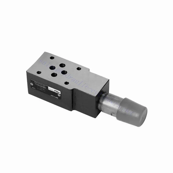
ZDB NG6
• 三明治式结构
• 安装面符合 DIN 24340 A 和 ISO 4401 标准
• Used in screw connection, Used for bottom sub-plate mounting
• 四个压力范围
• 5 circuit options
• 两种调节方式:旋钮、带保护盖的调节螺丝
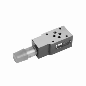
ZDB NG10
• 三明治式结构
• 安装面符合 DIN 24340 A 和 ISO 4401 标准
• Used in screw connection, Used for bottom sub-plate mounting
• 四个压力范围
• 6 circuit options
• With one or two inserted overflow valves
• Two adjustment types: knob, adjustment screw with protection cap
ZDB NG16、22
• 三明治式结构
• 安装面符合 DIN 24340 A 和 ISO 4401 标准
• Used in screw connection, Used for bottom sub-plate mounting
• 四个压力范围
• 5 circuit options
• With one or two inserted overflow valves
• One adjustment type: adjustment screw with protection cap
ZDBD NG6-32
• 三明治式结构
• 安装面符合 DIN 24340 A 和 ISO 4401 标准
• Used in screw connection, Used for bottom sub-plate mounting
• Three pressure ranges
• 4 circuit options
• With one or two inserted overflow valves
• One adjustment type: adjustment screw with protection cap
Usage Method Of ZDB/ZDBD Series Pilot Operated Pressure Relief Hydraulic Valve:
- 系统分析:
- 对液压系统进行全面分析,以确定具体的压力控制要求。
- 考虑最大工作压力、所需压力范围和流量。
- 阀门选择:
- Select the appropriate ZDB/ZDBD series hydraulic valve variant based on the system’s pressure control specifications.
- 考虑压力等级、流量以及与其他系统组件的兼容性。
- 安装:
- Follow the manufacturer’s instructions to correctly install the ZDB/ZDBD series pilot-operated pressure relief hydraulic valve in the hydraulic system.
- Ensure proper alignment and secure connection to prevent leaks and optimize performance.
- 压力调节:
- Adjust the valve’s control pilot to set the desired pressure relief level.
- Refer to the valve’s technical documentation for guidance on accurately adjusting the pilot pressure.
How Does A Hydraulic Priority Valve Work?
A hydraulic priority valve, also known as a flow divider or flow combiner, is a component used in hydraulic systems to allocate priority flow to specific circuits or actuators. Its primary function is to ensure that a predetermined amount of hydraulic fluid is supplied to a high-priority circuit or actuator before distributing the remaining flow to lower-priority circuits. Let’s explore how a hydraulic priority valve works:
- Valve Configuration:
- A hydraulic priority valve typically consists of a valve body, a spool, and various ports for fluid inlet and outlet.
- 流量调节:
- The priority valve receives hydraulic fluid from the main pump or power source.
- It regulates fluid flow based on the system’s specific requirements.
- Priority Port:
- The valve designates one or more ports as the priority port(s) where high-priority circuits or actuators are connected.
- These priority ports receive the initial flow allocation before the remaining flow is distributed to other ports.
- Spool Position:
- The position of the spool within the valve determines the flow distribution between the priority and secondary circuits.
- When the spool is in a neutral or centered position, the flow is blocked or restricted to all ports.
- Priority Flow Allocation:
- As hydraulic fluid enters the valve, it first reaches the priority port(s).
- The spool is designed to provide a predetermined flow rate to the high-priority circuit(s) connected to these ports.
- Remaining Flow Distribution:
- After the priority flow is allocated, the excess or remaining flow is diverted to the secondary ports connected to lower-priority circuits or actuators.
- The spool position allows the fluid to flow freely to these secondary circuits, ensuring they receive an adequate supply.
- 压力补偿:
- Hydraulic priority valves often incorporate pressure compensation mechanisms to maintain consistent flow rates regardless of load variations.
- These mechanisms adjust the spool position based on the pressure differential between the priority and secondary circuits.
工厂的能力和产能:
(1) 装配
我们拥有一流的自主研发装配平台。液压油缸生产车间拥有 4 条半自动提升油缸装配线和 1 条全自动倾斜油缸装配线,设计年生产能力 100 万支。特种油缸车间配备了各种规格的半自动清洗装配系统,设计年生产能力 20 万只,并配备了知名数控加工设备、加工中心、高精度油缸加工专用设备、机器人焊接机、自动清洗机、油缸自动装配机、自动喷漆生产线等。现有关键设备 300 多台(套)。设备资源的优化配置和高效利用,保证了产品的精度要求,满足了产品的高质量需求。


(2) 机加工
加工车间配备了定制的斜轨车削中心、加工中心、高速珩磨机、焊接机器人及其他相关设备,可加工最大内径 400 毫米、最大长度 6 米的气缸管。

(3) 焊接

(4) 油漆和涂料
配备中小型圆筒自动水性漆喷涂线,实现机器人自动上下料和自动喷涂,设计产能为每班 4000 件;
我们还拥有一条由动力链驱动的大型油缸半自动喷漆生产线,设计产能为每班 60 箱。


(5) 测试
我们拥有一流的检验设施和试验台,确保气缸的性能符合要求。

我们是最好的液压缸制造商之一。我们能够提供全面的液压缸。我们还提供相应的 农用齿轮箱凭借卓越的产品质量和售后服务,我们的产品远销世界各地,赢得了良好的声誉。我们欢迎国内外客户与我们联系洽谈业务、交流信息,并 与我们合作!
液压缸应用:
