4WRE(E) Series Proportional Directional Hydraulic Valve
4WRE(E) Series Proportional Directional Hydraulic Valve
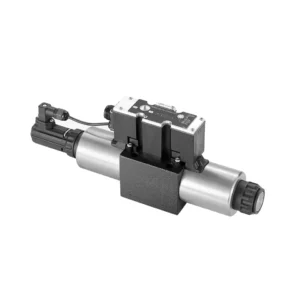
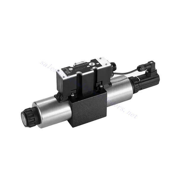
The 4WRE(E) series proportional directional hydraulic valve is a cutting-edge hydraulic component designed to deliver precise control and exceptional performance in hydraulic systems. This valve utilizes advanced proportional control technology to ensure accurate flow regulation and seamless directional changes.
The 4WRE(E) series proportional directional hydraulic valve empowers hydraulic systems with precise flow control, versatile directional changes, and energy efficiency. Its proportional control technology enables accurate and responsive flow adjustment, while the high flow capacity ensures reliable performance even in demanding applications. By following the recommended usage methods and maintenance guidelines, you can maximize the benefits and longevity of the 4WRE(E) series valve, elevating your hydraulic system to new levels of precision and performance. Upgrade your hydraulic setup today and experience the power of the 4WRE(E) series proportional directional hydraulic valve.
4WRE(E) Series Proportional Directional Hydraulic Valve Key Characteristics:
- Proportional Control Technology:
- The 4WRE(E) series valve features advanced proportional control technology, allowing for precise and proportional flow adjustment according to control signals.
- This feature enables accurate and responsive control, resulting in improved system performance and efficiency.
- Versatile Directional Control:
- With its proportional directional control capability, this valve offers versatile control over hydraulic fluid direction.
- It allows for seamless activation and deactivation of hydraulic components such as cylinders, motors, and actuators in different directions, enhancing system flexibility and productivity.
- Vysoká průtoková kapacita:
- The 4WRE(E) series valve is designed to handle high flow rates, making it suitable for applications requiring substantial hydraulic power.
- Jeho robustní konstrukce zajišťuje spolehlivý výkon i za náročných podmínek a poskytuje konzistentní a efektivní regulaci průtoku.
- Energetická účinnost:
- By employing advanced flow control mechanisms, this valve minimizes pressure drops and optimizes energy usage.
- Pomáhá snižovat spotřebu energie, což vede k úsporám nákladů a přínosům pro životní prostředí.
4WRE(E) Series Proportional Directional Hydraulic Valve Parameter:
| Hydraulické | ||||
| Montážní poloha | optional, preferably horizontal | |||
| Velikost | 6 | 10 | ||
| Hmotnost | 4WRE…L2X | kg | 2.2 | 6.3 |
| 4WREE…L2X | 2.4 | 6.5 | ||
| Nominal flow qnom at Δp = 10 bar | l/min | 8 16 32 | 25 50 75 | |
| Hystereze | % | ≤0.1 | ||
| Reversal span | % | ≤0.05 | ||
| Opakovatelnost | % | ≤0.05 | ||
| Max. provozní tlak | Port s A B P | bar | 315 | |
| Přístav T | bar | 210 | ||
| Tekutina | Minerální olej vhodný pro těsnění NBR a FKM | |||
| Fosfátový ester pro těsnění FKM | ||||
| Ambient air temperature range | 4WRA…L2X | ℃ | -20℃ to 70℃ (-4°F to 158°F) | |
| 4WRAE…L2X | ℃ | -20℃ to 50℃ (-4°F to 122°F) | ||
| Rozsah viskozity | mm²/s | 20 to 380 (preferably 30 to 46) | ||
| Stupeň kontaminace | NAS1638 class9 or ISO 4406 class 20/18/15 | |||
| Elektrické údaje | ||||
| 1)solenoid | ||||
| Velikost | 6 | 10 | ||
| Typ napětí | DC | |||
| Signál řídicí hodnoty | ±10V or 4~20mA | |||
| Max.current per solenoid | A | 2.5 | ||
| Odpor cívky | Cold value | Ω | 2.7 | 3.7 |
| Max. teplá hodnota | 4.05 | 5.55 | ||
| Duty | % | ED 100% | ||
| Teplota cívky | ℃ | 150 | ||
| Ochrana ventilu dle EN 60529 | Krytí IP 65 | |||
| 2) Control electronics | ||||
| Ampilfier | 4WRE…L2X | VT-VSPA2-L2X | ||
| 4WREE…L2X | integrated(OBE) | |||
| Operating voltage | Nominal voltage | VDC | 24 | |
| Lower limiting value | PROTI | 19.4 | ||
| Upper limiting value | PROTI | 35 | ||
| Amplifier current consumption | Imax | A | < 2 | |
| Imax | A | 3 | ||
4WRE(E) Series Proportional Directional Hydraulic Valve Advantages:
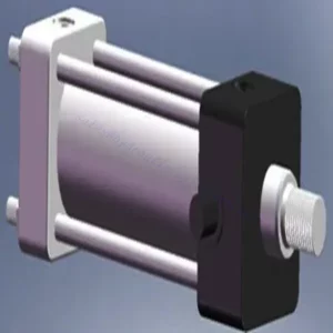
• Direct-acting proportional directional valve, used to control the flow and direction of liquid flow
• Panel type installation
• The proportional solenoid actuates the valve core through the threaded connection, and the coil can be removed separately
• Spool position feedback
• Optional with built-in amplifier, 4WRAE…L2X type input can be A1 or F1
• Supporting supply of external amplifier
Usage Method Of 4WRE(E) Series Proportional Directional Hydraulic Valve:
- Vyhodnocení systému:
- Vyhodnoťte svůj hydraulický systém a určete specifické požadavky na průtok a směrové řízení.
- Determine if the 4WRE(E) series valve is suitable based on its flow capacity, pressure rating, and compatibility with your system.
- Výběr ventilu:
- Select the appropriate variant of the 4WRE(E) series valve based on your system parameters, flow requirements, and directional control needs.
- Zvažte faktory, jako je maximální průtok, jmenovitý tlak, doba odezvy a provozní podmínky.
- Instalace:
- Follow the manufacturer’s installation instructions carefully, ensuring proper alignment and secure mounting of the valve.
- Pro zajištění optimálního výkonu vytvořte bezproblémové spoje a zajistěte správné směrování proudění.
- Připojení řídicího signálu:
- Připojte vodiče řídicího signálu ventilu k vhodnému řídicímu zařízení, jako je proporcionální zesilovač nebo elektronická řídicí jednotka.
- Pro přesné a citlivé ovládání zajistěte správné zapojení a kompatibilitu mezi ventilem a ovládacím zařízením.
How To Adjust Valves With Hydraulic Lifters?
Adjusting valve lash on hydraulic lifters is a crucial maintenance task to ensure proper engine performance and prevent issues such as noisy valves or reduced power. Here’s a step-by-step guide on how to adjust valve lash on hydraulic lifters:
- Příprava:
- Ensure the engine is off and cool before starting the adjustment process.
- Familiarize yourself with the engine’s firing order and the specific valve lash specifications provided by the manufacturer for your engine model.
- Identify the Correct Cylinder:
- Locate the firing position of the engine by referring to the engine’s firing order diagram.
- Identify the cylinder that corresponds to the specific valve you want to adjust.
- Umístění válce:
- Rotate the engine crankshaft manually using a socket wrench or the engine’s built-in turning mechanism.
- Position the cylinder you want to adjust at the top dead center (TDC) on the compression stroke. You can do this by aligning the timing marks on the crankshaft pulley or using a piston stop tool.
- Loosen the Rocker Arm:
- Locate the rocker arm on the specific valve you want to adjust.
- Loosen the rocker arm nut or adjuster screw using an appropriate wrench or socket.
- Adjust the Valve Lash:
- With the rocker arm loose, you can now adjust the valve lash. The valve lash is the clearance between the rocker arm and the valve stem.
- Use a feeler gauge to measure the existing valve lash. Insert the appropriate thickness gauge between the rocker arm and the valve stem.
- If the clearance is too tight, meaning the feeler gauge does not fit or has excessive resistance, you need to increase the valve lash. If the clearance is too loose, meaning the feeler gauge slides in too easily, you need to decrease the valve lash.
- To adjust the valve lash, tighten or loosen the rocker arm nut or adjuster screw accordingly. Refer to the manufacturer’s specifications for the recommended amount of adjustment to be made.
- Recheck the Valve Lash:
- After making the adjustment, recheck the valve lash using the feeler gauge to ensure it falls within the recommended specifications.
- Repeat the adjustment process if necessary until the correct valve lash is achieved.
- Repeat for Other Cylinders:
- Proceed to the next cylinder in the firing order and repeat steps 4 to 6 for each cylinder you want to adjust.
- Remember to rotate the crankshaft and position each cylinder at TDC on the compression stroke before adjusting its valve lash.
- Secure the Rocker Arm:
- Once the valve lash is properly adjusted for each cylinder, tighten the rocker arm nut or adjuster screw to the manufacturer’s recommended torque specification.
- Double-check that the valve lash remains within the specified range after tightening.
- Závěrečné kontroly:
- Rotate the engine crankshaft a few times to ensure smooth rotation and check for any unusual noises or resistance.
- Start the engine and listen for any abnormal valve noises. If you hear excessive tapping or knocking, recheck the valve lash adjustment.
Schopnosti a kapacita továrny:
(1) Montáž
Disponujeme prvotřídní nezávislou výzkumnou a vývojovou montážní platformou. Dílna na výrobu hydraulických válců má čtyři poloautomatické montážní linky pro zvedací válce a jednu automatickou montážní linku pro naklápěcí válce s projektovanou roční výrobní kapacitou 1 milion kusů. Dílna na speciální válce je vybavena poloautomatickým čisticím montážním systémem s různými specifikacemi a projektovanou roční výrobní kapacitou 200 000 kusů a je vybavena známým CNC obráběcím zařízením, obráběcím centrem, vysoce přesným speciálním zařízením pro zpracování válců, robotickým svařovacím strojem, automatickým čisticím strojem, automatickým montážním strojem pro válce a automatickou lakovací výrobní linkou. Stávající kritické vybavení má více než 300 sad. Optimální alokace a efektivní využití zdrojů zařízení zajišťuje požadavky na přesnost výrobků a splňuje požadavky na vysokou kvalitu výrobků.


(2) Obrábění
Obrobna je vybavena zakázkovým soustružnickým centrem pro šikmé kolejnice, obráběcím centrem, vysokorychlostním honovacím strojem, svařovacím robotem a dalším souvisejícím zařízením, které zvládne obrábění válcových trubek s maximálním vnitřním průměrem 400 mm a maximální délkou 6 metrů.

(3) Svařování

(4) Lakování a nátěry
S malými a středními válcovými automatickými linkami na nanášení barev na vodní bázi, pro dosažení automatického robotického nakládání a vykládání a automatického stříkání, je konstrukční kapacita 4000 kusů za směnu;
Máme také poloautomatickou linku na výrobu barev pro velké tlakové lahve poháněné řetězem s konstrukční kapacitou 60 lahví za směnu.


(5) Testování
Disponujeme prvotřídními inspekčními zařízeními a zkušebními laboratořemi, abychom zajistili, že výkon válce splňuje požadavky.

Jsme jedním z nejlepších výrobců hydraulických válců. Nabízíme komplexní hydraulické válce. Dodáváme také odpovídající zemědělské převodovkyNaše výrobky jsme exportovali klientům po celém světě a díky vynikající kvalitě výrobků a poprodejnímu servisu jsme si získali dobrou pověst. Vítáme zákazníky doma i v zahraničí, kteří nás kontaktují za účelem vyjednávání obchodních příležitostí, výměny informací a spolupracujte s námi!