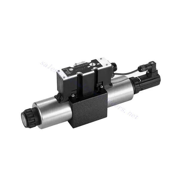
4WRE(E) Series Proportional Directional Hydraulic Valve
4WRE(E) Series Proportional Directional Hydraulic Valve
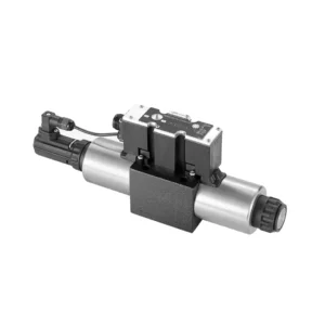
The 4WRE(E) series proportional directional hydraulic valve is a cutting-edge hydraulic component designed to deliver precise control and exceptional performance in hydraulic systems. This valve utilizes advanced proportional control technology to ensure accurate flow regulation and seamless directional changes.
The 4WRE(E) series proportional directional hydraulic valve empowers hydraulic systems with precise flow control, versatile directional changes, and energy efficiency. Its proportional control technology enables accurate and responsive flow adjustment, while the high flow capacity ensures reliable performance even in demanding applications. By following the recommended usage methods and maintenance guidelines, you can maximize the benefits and longevity of the 4WRE(E) series valve, elevating your hydraulic system to new levels of precision and performance. Upgrade your hydraulic setup today and experience the power of the 4WRE(E) series proportional directional hydraulic valve.
4WRE(E) Series Proportional Directional Hydraulic Valve Key Characteristics:
- Proportional Control Technology:
- The 4WRE(E) series valve features advanced proportional control technology, allowing for precise and proportional flow adjustment according to control signals.
- This feature enables accurate and responsive control, resulting in improved system performance and efficiency.
- Versatile Directional Control:
- With its proportional directional control capability, this valve offers versatile control over hydraulic fluid direction.
- It allows for seamless activation and deactivation of hydraulic components such as cylinders, motors, and actuators in different directions, enhancing system flexibility and productivity.
- Висока пропускна здатність:
- The 4WRE(E) series valve is designed to handle high flow rates, making it suitable for applications requiring substantial hydraulic power.
- Його міцна конструкція забезпечує надійну роботу навіть у складних умовах, забезпечуючи стабільний та ефективний контроль потоку.
- Energy Efficiency:
- By employing advanced flow control mechanisms, this valve minimizes pressure drops and optimizes energy usage.
- Це допомагає зменшити споживання енергії, що призводить до економії коштів та покращує навколишнє середовище.
4WRE(E) Series Proportional Directional Hydraulic Valve Parameter:
| Гідравлічний | ||||
| Положення встановлення | необов'язково, бажано горизонтально | |||
| Розмір | 6 | 10 | ||
| Вага | 4WRE…L2X | кг | 2.2 | 6.3 |
| 4WREE…L2X | 2.4 | 6.5 | ||
| Nominal flow qnom at Δp = 10 bar | л/хв | 8 16 32 | 25 50 75 | |
| Гістерезис | % | ≤0.1 | ||
| Reversal span | % | ≤0.05 | ||
| Повторюваність | % | ≤0.05 | ||
| Макс. робочий тиск | Port s A B P | бар | 315 | |
| Порт Т | бар | 210 | ||
| Рідина | Мінеральна олива, що підходить для ущільнень NBR та FKM | |||
| Фосфатний ефір для ущільнення FKM | ||||
| Ambient air temperature range | 4WRA…L2X | ℃ | -20℃ to 70℃ (-4°F to 158°F) | |
| 4WRAE…L2X | ℃ | -20℃ to 50℃ (-4°F to 122°F) | ||
| Діапазон в'язкості | мм²/с | від 20 до 380 (бажано від 30 до 46) | ||
| Ступінь забруднення | NAS1638 class9 or ISO 4406 class 20/18/15 | |||
| Електричні дані | ||||
| 1)solenoid | ||||
| Розмір | 6 | 10 | ||
| Тип напруги | Округ Колумбія | |||
| Сигнал командного значення | ±10V or 4~20mA | |||
| Max.current per solenoid | А | 2.5 | ||
| Опір котушки | Cold value | Ом | 2.7 | 3.7 |
| Макс. значення тепла | 4.05 | 5.55 | ||
| Обов'язок | % | ED 100% | ||
| Температура котушки | ℃ | 150 | ||
| Захист клапана згідно з EN 60529 | IP65 | |||
| 2) Control electronics | ||||
| Підсилювач | 4WRE…L2X | VT-VSPA2-L2X | ||
| 4WREE…L2X | integrated(OBE) | |||
| Робоча напруга | Номінальна напруга | В постійного струму | 24 | |
| Нижнє граничне значення | В | 19.4 | ||
| Верхнє граничне значення | В | 35 | ||
| Споживання струму підсилювача | IMAX | А | < 2 | |
| IMAX | А | 3 | ||
4WRE(E) Series Proportional Directional Hydraulic Valve Advantages:
• Direct-acting proportional directional valve, used to control the flow and direction of liquid flow
• Панельний монтаж
• The proportional solenoid actuates the valve core through the threaded connection, and the coil can be removed separately
• Spool position feedback
• Optional with built-in amplifier, 4WRAE…L2X type input can be A1 or F1
• Підтримка живлення зовнішнього підсилювача
Usage Method Of 4WRE(E) Series Proportional Directional Hydraulic Valve:
- Оцінка системи:
- Оцініть свою гідравлічну систему та визначте конкретні вимоги до керування потоком і напрямком.
- Determine if the 4WRE(E) series valve is suitable based on its flow capacity, pressure rating, and compatibility with your system.
- Вибір клапана:
- Select the appropriate variant of the 4WRE(E) series valve based on your system parameters, flow requirements, and directional control needs.
- Враховуйте такі фактори, як максимальна витрата, номінальний тиск, час відгуку та умови експлуатації.
- Встановлення:
- Уважно дотримуйтесь інструкцій виробника з встановлення, забезпечуючи правильне вирівнювання та надійне кріплення клапана.
- Make leak-free connections and ensure correct flow direction alignment to guarantee optimal performance.
- Control Signal Connection:
- Підключіть дроти керуючого сигналу клапана до відповідного пристрою керування, такого як пропорційний підсилювач або електронний блок керування.
- Забезпечте правильне підключення та сумісність між клапаном та пристроєм керування для точного та чутливого керування.
How To Adjust Valves With Hydraulic Lifters?
Adjusting valve lash on hydraulic lifters is a crucial maintenance task to ensure proper engine performance and prevent issues such as noisy valves or reduced power. Here’s a step-by-step guide on how to adjust valve lash on hydraulic lifters:
- Підготовка:
- Ensure the engine is off and cool before starting the adjustment process.
- Familiarize yourself with the engine’s firing order and the specific valve lash specifications provided by the manufacturer for your engine model.
- Identify the Correct Cylinder:
- Locate the firing position of the engine by referring to the engine’s firing order diagram.
- Identify the cylinder that corresponds to the specific valve you want to adjust.
- Розташування циліндра:
- Rotate the engine crankshaft manually using a socket wrench or the engine’s built-in turning mechanism.
- Position the cylinder you want to adjust at the top dead center (TDC) on the compression stroke. You can do this by aligning the timing marks on the crankshaft pulley or using a piston stop tool.
- Loosen the Rocker Arm:
- Locate the rocker arm on the specific valve you want to adjust.
- Loosen the rocker arm nut or adjuster screw using an appropriate wrench or socket.
- Adjust the Valve Lash:
- With the rocker arm loose, you can now adjust the valve lash. The valve lash is the clearance between the rocker arm and the valve stem.
- Use a feeler gauge to measure the existing valve lash. Insert the appropriate thickness gauge between the rocker arm and the valve stem.
- If the clearance is too tight, meaning the feeler gauge does not fit or has excessive resistance, you need to increase the valve lash. If the clearance is too loose, meaning the feeler gauge slides in too easily, you need to decrease the valve lash.
- To adjust the valve lash, tighten or loosen the rocker arm nut or adjuster screw accordingly. Refer to the manufacturer’s specifications for the recommended amount of adjustment to be made.
- Recheck the Valve Lash:
- After making the adjustment, recheck the valve lash using the feeler gauge to ensure it falls within the recommended specifications.
- Repeat the adjustment process if necessary until the correct valve lash is achieved.
- Repeat for Other Cylinders:
- Proceed to the next cylinder in the firing order and repeat steps 4 to 6 for each cylinder you want to adjust.
- Remember to rotate the crankshaft and position each cylinder at TDC on the compression stroke before adjusting its valve lash.
- Secure the Rocker Arm:
- Once the valve lash is properly adjusted for each cylinder, tighten the rocker arm nut or adjuster screw to the manufacturer’s recommended torque specification.
- Double-check that the valve lash remains within the specified range after tightening.
- Заключні перевірки:
- Rotate the engine crankshaft a few times to ensure smooth rotation and check for any unusual noises or resistance.
- Start the engine and listen for any abnormal valve noises. If you hear excessive tapping or knocking, recheck the valve lash adjustment.
Можливості та потужність заводу:
(1) Асамблея
Ми маємо першокласну незалежну платформу для досліджень та розробок. Цех виробництва гідравлічних циліндрів має чотири напівавтоматичні лінії складання підйомних циліндрів та одну автоматичну лінію складання нахилених циліндрів з проектною річною виробничою потужністю 1 мільйон одиниць. Цех спеціальних циліндрів оснащений різними специфікаціями напівавтоматичної системи очищення та складання з проектною річною виробничою потужністю 200 000 одиниць, а також оснащений відомим обладнанням з ЧПУ, обробним центром, високоточним спеціальним обладнанням для обробки циліндрів, роботизованим зварювальним апаратом, автоматичною машиною очищення, автоматичною машиною складання циліндрів та автоматичною виробничою лінією фарбування. Існуюче критично важливе обладнання налічує понад 300 комплектів. Оптимальний розподіл та ефективне використання ресурсів обладнання забезпечує вимоги до точності продукції та задоволення потреб у високій якості продукції.


(2) Механічна обробка
Механічний цех оснащений спеціалізованим токарним центром для похилих рейок, обробним центром, високошвидкісним хонінгувальним верстатом, зварювальним роботом та іншим супутнім обладнанням, яке може обробляти циліндричні труби з максимальним внутрішнім діаметром 400 мм та максимальною довжиною 6 метрів.

(3) Зварювання

(4) Фарбування та покриття
З малими та середніми циліндричними автоматичними лініями нанесення фарби на водній основі, для досягнення автоматичного завантаження та розвантаження роботів та автоматичного розпилення, проектна потужність 4000 штук за зміну;
У нас також є напівавтоматична лінія з виробництва фарби для великих балонів, що живиться від ланцюга, з проектною потужністю 60 корпусів за зміну.


(5) Тестування
Ми маємо першокласне обладнання для інспекції та випробувальні стенди, щоб гарантувати, що характеристики циліндра відповідають вимогам.

Ми є одним з найкращих виробників гідравлічних циліндрів. Ми можемо запропонувати комплексні гідравлічні циліндри. Ми також надаємо відповідні сільськогосподарські коробки передачМи експортуємо нашу продукцію клієнтам по всьому світу та заслужили гарну репутацію завдяки високій якості нашої продукції та післяпродажному обслуговуванню. Ми раді вітати клієнтів як удома, так і за кордоном, щоб зв'язатися з нами для ведення бізнесу, обміну інформацією та... співпрацюйте з нами!


