4WRE(E)-seriens proportionella riktningsventil för hydraulik
4WRE(E)-seriens proportionella riktningsventil för hydraulik
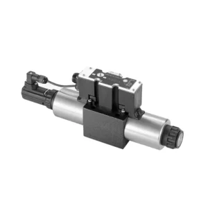
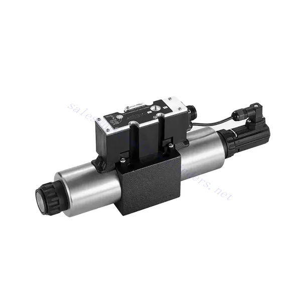
The 4WRE(E) series proportional directional hydraulic valve is a cutting-edge hydraulic component designed to deliver precise control and exceptional performance in hydraulic systems. This valve utilizes advanced proportional control technology to ensure accurate flow regulation and seamless directional changes.
The 4WRE(E) series proportional directional hydraulic valve empowers hydraulic systems with precise flow control, versatile directional changes, and energy efficiency. Its proportional control technology enables accurate and responsive flow adjustment, while the high flow capacity ensures reliable performance even in demanding applications. By following the recommended usage methods and maintenance guidelines, you can maximize the benefits and longevity of the 4WRE(E) series valve, elevating your hydraulic system to new levels of precision and performance. Upgrade your hydraulic setup today and experience the power of the 4WRE(E) series proportional directional hydraulic valve.
4WRE(E) Series Proportional Directional Hydraulic Valve Key Characteristics:
- Proportional Control Technology:
- The 4WRE(E) series valve features advanced proportional control technology, allowing for precise and proportional flow adjustment according to control signals.
- This feature enables accurate and responsive control, resulting in improved system performance and efficiency.
- Versatile Directional Control:
- With its proportional directional control capability, this valve offers versatile control over hydraulic fluid direction.
- It allows for seamless activation and deactivation of hydraulic components such as cylinders, motors, and actuators in different directions, enhancing system flexibility and productivity.
- Hög flödeskapacitet:
- The 4WRE(E) series valve is designed to handle high flow rates, making it suitable for applications requiring substantial hydraulic power.
- Dess robusta konstruktion säkerställer tillförlitlig prestanda även under krävande förhållanden, vilket ger en konsekvent och effektiv flödeskontroll.
- Energieffektivitet:
- By employing advanced flow control mechanisms, this valve minimizes pressure drops and optimizes energy usage.
- Det bidrar till att minska energiförbrukningen, vilket resulterar i kostnadsbesparingar och miljöfördelar.
4WRE(E) Series Proportional Directional Hydraulic Valve Parameter:
| Hydraulisk | ||||
| Installationsposition | valfritt, helst horisontellt | |||
| Storlek | 6 | 10 | ||
| Vikt | 4WRE…L2X | kg | 2.2 | 6.3 |
| 4WREE…L2X | 2.4 | 6.5 | ||
| Nominal flow qnom at Δp = 10 bar | l/min | 8 16 32 | 25 50 75 | |
| Hysteres | % | ≤0.1 | ||
| Reversal span | % | ≤0.05 | ||
| Repeterbarhet | % | ≤0.05 | ||
| Max. driftstryck | Port s A B P | bar | 315 | |
| Port T | bar | 210 | ||
| Vätska | Mineralolja lämplig för NBR- och FKM-tätningar | |||
| Fosfatester för FKM-tätning | ||||
| Ambient air temperature range | 4WRA…L2X | ℃ | -20℃ to 70℃ (-4°F to 158°F) | |
| 4WRAE…L2X | ℃ | -20℃ to 50℃ (-4°F to 122°F) | ||
| Viskositetsområde | mm²/s | 20 till 380 (helst 30 till 46) | ||
| Grad av kontaminering | NAS1638 class9 or ISO 4406 class 20/18/15 | |||
| Elektriska data | ||||
| 1)solenoid | ||||
| Storlek | 6 | 10 | ||
| Spänningstyp | likström | |||
| Kommandovärdessignal | ±10V or 4~20mA | |||
| Max.current per solenoid | En | 2.5 | ||
| Spolmotstånd | Cold value | Ω | 2.7 | 3.7 |
| Max. värmevärde | 4.05 | 5.55 | ||
| Tull | % | ED 100% | ||
| Spoltemperatur | ℃ | 150 | ||
| Ventilskydd enligt EN 60529 | IP65 | |||
| 2) Control electronics | ||||
| Förstärkare | 4WRE…L2X | VT-VSPA2-L2X | ||
| 4WREE…L2X | integrated(OBE) | |||
| Driftspänning | Nominell spänning | VDC | 24 | |
| Nedre gränsvärde | V | 19.4 | ||
| Övre gränsvärde | V | 35 | ||
| Förstärkarens strömförbrukning | Imax | En | < 2 | |
| Imax | En | 3 | ||
4WRE(E) Series Proportional Directional Hydraulic Valve Advantages:
• Direct-acting proportional directional valve, used to control the flow and direction of liquid flow
• Panelliknande installation
• Den proportionella solenoiden aktiverar ventilkärnan via den gängade anslutningen, och spolen kan tas bort separat
• Spool position feedback
• Optional with built-in amplifier, 4WRAE…L2X type input can be A1 or F1
• Stödjer matning av extern förstärkare
Usage Method Of 4WRE(E) Series Proportional Directional Hydraulic Valve:
- Systemutvärdering:
- Utvärdera ditt hydraulsystem och identifiera de specifika kraven för flödes- och riktningskontroll.
- Determine if the 4WRE(E) series valve is suitable based on its flow capacity, pressure rating, and compatibility with your system.
- Ventilval:
- Select the appropriate variant of the 4WRE(E) series valve based on your system parameters, flow requirements, and directional control needs.
- Tänk på faktorer som maximal flödeshastighet, tryckklassning, reaktionstid och driftsförhållanden.
- Installation:
- Följ tillverkarens installationsanvisningar noggrant och säkerställ korrekt inriktning och säker montering av ventilen.
- Make leak-free connections and ensure correct flow direction alignment to guarantee optimal performance.
- Control Signal Connection:
- Anslut ventilens styrsignalledningar till en lämplig styrenhet, såsom en proportionalförstärkare eller elektronisk styrenhet.
- Säkerställ korrekt kabeldragning och kompatibilitet mellan ventilen och styrenheten för noggrann och responsiv styrning.
How To Adjust Valves With Hydraulic Lifters?
Adjusting valve lash on hydraulic lifters is a crucial maintenance task to ensure proper engine performance and prevent issues such as noisy valves or reduced power. Here’s a step-by-step guide on how to adjust valve lash on hydraulic lifters:
- Förberedelse:
- Ensure the engine is off and cool before starting the adjustment process.
- Familiarize yourself with the engine’s firing order and the specific valve lash specifications provided by the manufacturer for your engine model.
- Identify the Correct Cylinder:
- Locate the firing position of the engine by referring to the engine’s firing order diagram.
- Identify the cylinder that corresponds to the specific valve you want to adjust.
- Placera cylindern:
- Rotate the engine crankshaft manually using a socket wrench or the engine’s built-in turning mechanism.
- Position the cylinder you want to adjust at the top dead center (TDC) on the compression stroke. You can do this by aligning the timing marks on the crankshaft pulley or using a piston stop tool.
- Loosen the Rocker Arm:
- Locate the rocker arm on the specific valve you want to adjust.
- Loosen the rocker arm nut or adjuster screw using an appropriate wrench or socket.
- Adjust the Valve Lash:
- With the rocker arm loose, you can now adjust the valve lash. The valve lash is the clearance between the rocker arm and the valve stem.
- Use a feeler gauge to measure the existing valve lash. Insert the appropriate thickness gauge between the rocker arm and the valve stem.
- If the clearance is too tight, meaning the feeler gauge does not fit or has excessive resistance, you need to increase the valve lash. If the clearance is too loose, meaning the feeler gauge slides in too easily, you need to decrease the valve lash.
- To adjust the valve lash, tighten or loosen the rocker arm nut or adjuster screw accordingly. Refer to the manufacturer’s specifications for the recommended amount of adjustment to be made.
- Recheck the Valve Lash:
- After making the adjustment, recheck the valve lash using the feeler gauge to ensure it falls within the recommended specifications.
- Repeat the adjustment process if necessary until the correct valve lash is achieved.
- Repeat for Other Cylinders:
- Proceed to the next cylinder in the firing order and repeat steps 4 to 6 for each cylinder you want to adjust.
- Remember to rotate the crankshaft and position each cylinder at TDC on the compression stroke before adjusting its valve lash.
- Secure the Rocker Arm:
- Once the valve lash is properly adjusted for each cylinder, tighten the rocker arm nut or adjuster screw to the manufacturer’s recommended torque specification.
- Double-check that the valve lash remains within the specified range after tightening.
- Slutkontroller:
- Rotate the engine crankshaft a few times to ensure smooth rotation and check for any unusual noises or resistance.
- Start the engine and listen for any abnormal valve noises. If you hear excessive tapping or knocking, recheck the valve lash adjustment.
Fabrikens kapacitet och kapacitet:
(1) Montering
Vi har en förstklassig oberoende forsknings- och utvecklingsplattform. Verkstaden för tillverkning av hydraulcylindrar har fyra halvautomatiska monteringslinjer för lyftcylindrar och en automatisk monteringslinje för tiltcylindrar, med en planerad årlig produktionskapacitet på 1 miljon enheter. Specialcylinderverkstaden är utrustad med olika specifikationer för ett halvautomatiskt rengöringsmonteringssystem med en planerad årlig produktionskapacitet på 200 000 och utrustad med känd CNC-bearbetningsutrustning, ett fleroperationscenter, en specialutrustning för högprecisionscylindrar, en robotsvetsmaskin, en automatisk rengöringsmaskin, en automatisk cylindermonteringsmaskin och en automatisk produktionslinje för målning. Befintlig kritisk utrustning på mer än 300 set (set). Optimal allokering och effektiv användning av utrustningsresurser säkerställer produkternas noggrannhetskrav och uppfyller produkternas höga kvalitetsbehov.


(2) Maskinbearbetning
Bearbetningsverkstaden är utrustad med en specialanpassad svarvcentral för lutande räls, bearbetningscenter, höghastighetshönsmaskin, svetsrobot och annan relaterad utrustning, som kan hantera bearbetning av cylinderrör med en maximal innerdiameter på 400 mm och en maximal längd på 6 meter.

(3) Svetsning

(4) Målning och ytbehandling
Med små och medelstora cylindriska automatiska vattenbaserade färgbeläggningslinjer, för att uppnå automatisk robotlastning och lossning samt automatisk sprutning, är den designade kapaciteten 4000 stycken per skift;
Vi har även en halvautomatisk färgproduktionslinje för stora cylindrar som drivs av en släpkedja, med en designkapacitet på 60 lådor per skift.


(5) Testning
Vi har förstklassiga inspektionsanläggningar och testbäddar för att säkerställa att cylinderns prestanda uppfyller kraven.

Vi är en av de bästa tillverkarna av hydraulcylindrar. Vi kan erbjuda ett heltäckande utbud av hydraulcylindrar. Vi tillhandahåller även motsvarande jordbruksväxellådorVi har exporterat våra produkter till kunder över hela världen och fått ett gott rykte tack vare vår överlägsna produktkvalitet och kundservice. Vi välkomnar kunder både hemma och utomlands att kontakta oss för att förhandla affärer, utbyta information och samarbeta med oss!


