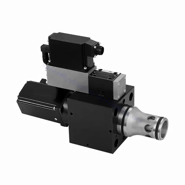
WRCE-Serie 2- und 3-Wege-Hydraulikventil mit hoher Ansprechgeschwindigkeit und hohem Durchfluss
Als einer der Hersteller, Lieferanten und Exporteure von mechanischen Produkten, bieten wir Hydraulikzylinder und viele andere Produkte an.
Bitte setzen Sie sich mit uns in Verbindung, um Einzelheiten zu erfahren.
Post:sales@hydraulic-cylinders.net
Hersteller, Lieferant und Exporteur von Hydraulikzylindern.
WRCE-Serie 2- und 3-Wege-Hydraulikventil mit hoher Ansprechgeschwindigkeit und hohem Durchfluss
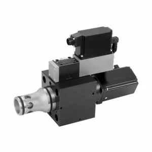
The WRCE series 2- and 3-way high-response flow hydraulic valve is a remarkable hydraulic component designed to deliver exceptional performance in fluid control applications. With its high-response flow capabilities, this valve revolutionizes hydraulic systems by providing precise and efficient flow control.
The WRCE series 2- and 3-way high-response flow hydraulic valve sets new standards in flow control precision and efficiency. With its high-response flow capabilities, compact design, and versatility, this valve empowers hydraulic systems to achieve optimal performance and energy efficiency. By following the recommended usage methods and maintenance guidelines, you can harness the full potential of the WRCE series valve and experience enhanced control and productivity in your hydraulic applications. Upgrade your hydraulic system today and unlock the advantages of efficiency and precision with the WRCE series 2- and 3-way high-response flow hydraulic valve.
WRCE Series 2-and 3-way High-response Flow Hydraulic Valve Key Characteristics:
- High-Response Flow:
- The WRCE series valve is engineered to offer high-response flow control, ensuring rapid and accurate adjustments to fluid flow rates.
- This characteristic enables precise control over hydraulic actuators, resulting in enhanced system performance, reduced energy consumption, and improved overall efficiency.
- Versatile 2- and 3-Way Configuration:
- This valve is available in both 2-way and 3-way configurations, providing flexibility to meet various hydraulic system requirements.
- The 2-way configuration allows for simple on/off control, while the 3-way design enables directional control, making it ideal for applications such as actuator extension and retraction.
- Kompaktes Design:
- The WRCE series valve features a compact design, making it suitable for installations where space is limited.
- This compact size allows easy integration into various hydraulic systems without compromising performance or functionality.
- High-Pressure Rating:
- This valve is built to withstand high-pressure environments, ensuring reliable operation even in demanding hydraulic applications.
- Its robust construction and high-pressure rating make it suitable for use in systems that require efficient flow control under extreme operating conditions.
WRCE Series 2-and 3-way High-response Flow Hydraulic Valve Parameter:
| Allgemein | |||||
| NS NG | 32 | 40 | 50 | ||
| Gewicht | kg | 11.2 | 17.3 | 24.6 | |
| Weight with shut-off valve …../…WK or …/…WL… | kg | 12.5 | 18.6 | 25.9 | |
| Size of the pilot control valve (pilot) | NG | 6 | 6 | 6 | |
| Einbaulage | Any, preferably horizontal | ||||
| Storage temperature range | ℃ | –20 to +80 | |||
| Umstände Temperaturbereich | ℃ | –20 to +50 | |||
| Hydraulic (measured with HLP32, ϑoil=40℃ ±5℃) | |||||
| Max. Betriebsdruck | – Main stagePort A、B | Bar | NS 32~40: 350,NS 50: 420 | ||
| – Pilot control valve port X | 315 | ||||
| – Pilot control valve port Y | 210 | ||||
| Rated flow Δp=5bar | – Specifications …S…L (linear) | L/min | 800 | 1200 | 2000 |
| – Specifications …S…R (linear with progressive fine control range) | 600 | 850 | 1400 | ||
| Nominal flow of pilot valve at Δp=70bar | L/min | 12 | 40 | 40 | |
| Leakage of pilot valve at P=100bar | L/min | 0.3 | 0.7 | 0.7 | |
| Hydraulikflüssigkeit | Mineral oil (HL,HLP) to DIN 51524 | ||||
| Hydraulic fluid temperature range | ℃ | 20 to +80;preferably +40 to +50 | |||
| Viskositätsbereich | mm2/S | 20 to 380;preferably 30 to 45 | |||
| Maximum admissible degree of contamination of the hydraulic fluid, cleanliness class according to ISO 4406 (c) | Class 20/18/15 | ||||
| Hysterese | % | ≤ 0.2 | |||
| Hysterese | % | ≤ 0.1 | |||
| Ansprechsensitivität | % | ≤ 0.1 | |||
| Response Time(step signa 0 ~ 100%) | MS | ≤ 20 | |||
| Elektrische Daten | |||||
| Spannungstyp | Direct voltage | ||||
| Type of signal | Analog | ||||
| Opening point calibration | % | ≦ 1 | |||
| Zero shift upon change of: | – Hydraulic fluid temperature | %/10K | ≦ 0.3 | ≦ 0.3 | ≦ 0.3 |
| – Pilot pressure in X | %/100bar | ≦ 0.7 | ≦ 0.7 | ≦ 0.7 | |
| – Return flow pressure in Y | %/bar | ≦ 0.3 | ≦ 0.3 | ≦ 0.3 | |
| The protection class of the valve according to EN60529 | IP65 with a mating connector mounted and locked | ||||
WRCE Series 2-and 3-way High-response Flow Hydraulic Valve Advantages:
• Pilot-operated two-stage cartridge high-frequency response throttle valve
• Suitable for closed-loop control of position, pressure, force and speed
• Pilot control valve: six-port direct-acting high-frequency response proportional valve with electric feedback
• Main stage: closed loop position control
• Integrated open loop and closed loop control electronics (OBE)
Usage Method Of WRCE Series 2-and 3-way High-response Flow Hydraulic Valve :
- Systembewertung:
- Evaluate your hydraulic system and determine the specific flow control requirements.
- Identify whether the WRCE series valve is compatible with your system based on factors such as flow rates, pressure ratings, and the desired control functions.
- Ventilauswahl:
- Select the appropriate variant of the WRCE series valve based on your system parameters and flow control needs.
- Consider factors such as flow capacity, pressure rating, response time, and compatibility with your specific application.
- Installation:
- Follow the manufacturer’s installation instructions carefully to ensure proper alignment and secure mounting of the valve.
- Make sure to create leak-free connections by using suitable hydraulic fittings, adapters, and seals. Tighten the connections adequately to prevent any fluid leaks.
- Integration von Steuersignalen:
- Connect the control signal lines of the valve to a suitable control device, such as a hydraulic control module, electronic control unit, or manual control lever.
- Ensure proper wiring and compatibility between the valve and control device to achieve accurate and responsive flow control.
How To Hook Up Hydraulic Control Valve?
To hook up a hydraulic control valve, follow these steps:
- Identify Valve Type: Determine the specific type of hydraulic control valve you are working with, such as a directional control valve, pressure control valve, or flow control valve. Ensure that the valve is suitable for your application and compatible with your hydraulic system.
- Gather Required Tools and Materials: Collect the necessary tools and materials, including appropriate hydraulic fittings, adapters, hoses, and wrenches. Refer to the manufacturer’s instructions for any specific tools or components needed.
- Bereiten Sie das Hydrauliksystem vor: Schalten Sie das Hydrauliksystem ab und entlasten Sie den Druck, indem Sie das Überdruckventil aktivieren oder die Hydraulikzylinder einfahren. Dieser Schritt ist für die Sicherheit von entscheidender Bedeutung und verhindert unbeabsichtigte Bewegungen oder das Austreten von Hydraulikflüssigkeit.
- Identify Flow Direction: Bestimmen Sie die Durchflussrichtung in Ihrem Hydrauliksystem. Normalerweise wird die Durchflussrichtung durch Pfeile auf den Hydraulikkomponenten angezeigt. Stellen Sie sicher, dass Sie die richtige Durchflussrichtung kennen, bevor Sie fortfahren.
- Locate Installation Point: Identify the optimal location to install the hydraulic control valve in your hydraulic system. Consider factors such as accessibility, proximity to the actuator or hydraulic component, and ease of operation. Ensure there is enough space for the valve to be mounted securely.
- Montieren Sie das Ventil: Securely mount the hydraulic control valve in the chosen location using appropriate brackets or clamps. Ensure the valve is positioned correctly, aligning the inlet and outlet ports with the flow direction. Follow the manufacturer’s instructions for the specific mounting requirements of your valve.
- Schließen Sie die Einlass- und Auslassanschlüsse an: Attach hydraulic hoses or tubing to the inlet and outlet ports of the hydraulic control valve. Use suitable hydraulic fittings and adapters to create a leak-free connection. Tighten the connections using wrenches to ensure a secure fit, but avoid over-tightening.
- Connect Control Lines: If your hydraulic control valve requires external control signals, connect the control lines from the control device, such as a joystick, lever, or solenoid, to the appropriate ports on the valve. Follow the manufacturer’s instructions for the correct wiring or connection configuration.
- Testen Sie das System: Once the hydraulic control valve is installed, slowly restore hydraulic system pressure. Test the system to ensure that the valve is functioning correctly. Operate the control device and observe the response of the hydraulic components to verify that the valve is controlling the flow, pressure, or direction as intended.
- Fine-tune and Adjust: Make any necessary adjustments to the hydraulic control valve to achieve the desired flow, pressure, or direction control. Refer to the manufacturer’s instructions for specific adjustment procedures. Regularly monitor the system for any leaks, pressure inconsistencies, or abnormal behavior.
Fähigkeit und Kapazität der Fabrik:
(1) Montage
Wir verfügen über eine erstklassige, unabhängige Forschungs- und Entwicklungsmontageplattform. Die Hydraulikzylinder-Produktionswerkstatt verfügt über vier halbautomatische Montagelinien für Hubzylinder und eine automatische Montagelinie für Kippzylinder mit einer geplanten jährlichen Produktionskapazität von 1 Million Stück. Die Spezialzylinderwerkstatt ist mit verschiedenen Spezifikationen eines halbautomatischen Reinigungsmontagesystems mit einer geplanten jährlichen Produktionskapazität von 200.000 ausgestattet und mit renommierten CNC-Bearbeitungsgeräten, einem Bearbeitungszentrum, einer hochpräzisen Spezialausrüstung für die Zylinderverarbeitung, einer Roboterschweißmaschine, einer automatischen Reinigungsmaschine, einer automatischen Zylindermontagemaschine und einer automatischen Lackierproduktionslinie ausgestattet. Es sind mehr als 300 Sets (Sätze) an kritischer Ausrüstung vorhanden. Die optimale Zuweisung und effiziente Nutzung der Ausrüstungsressourcen gewährleistet die Genauigkeitsanforderungen der Produkte und erfüllt die hohen Qualitätsanforderungen der Produkte.


(2) Bearbeitungen
Die Bearbeitungswerkstatt ist mit einem maßgeschneiderten Schrägschienen-Drehzentrum, einem Bearbeitungszentrum, einer Hochgeschwindigkeits-Honmaschine, einem Schweißroboter und anderen zugehörigen Geräten ausgestattet, die die Bearbeitung von Zylinderrohren mit einem maximalen Innendurchmesser von 400 mm und einer maximalen Länge von 6 Metern ermöglichen.

(3) Schweißen

(4) Malerei und Beschichtung
Mit kleinen und mittleren Zylinder automatische Lackieranlagen auf Wasserbasis, zu erreichen automatische Roboter Be-und Entladen und automatische Spritzen, die Design-Kapazität von 4000 Stück pro Schicht;
Wir verfügen auch über eine halbautomatische Lackieranlage für große Zylinder, die von einer Energiekette angetrieben wird und eine Kapazität von 60 Kisten pro Schicht hat.


(5) Prüfung
Wir verfügen über erstklassige Prüfeinrichtungen und Prüfstände, um sicherzustellen, dass die Leistung des Zylinders den Anforderungen entspricht.

Wir sind einer der besten Hydraulikzylinderhersteller. Wir können umfassende Hydraulikzylinder anbieten. Wir bieten auch entsprechende landwirtschaftliche Getriebe. Wir haben unsere Produkte an Kunden weltweit exportiert und uns aufgrund unserer hervorragenden Produktqualität und unseres Kundendienstes einen guten Ruf erworben. Wir begrüßen Kunden im In- und Ausland, die uns kontaktieren, um Geschäfte zu verhandeln, Informationen auszutauschen und mit uns zusammenarbeiten!
Hydraulischer Zylinder Anwendung:
