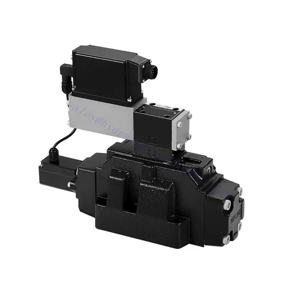
4WRLE Series Pilot Operated Proportional Directional Hydraulic Valve
4WRLE Series Pilot Operated Proportional Directional Hydraulic Valve
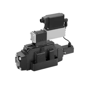
The 4WRLE series pilot-operated proportional directional hydraulic valve is a cutting-edge hydraulic component that revolutionizes fluid control in hydraulic systems. This valve combines pilot-operated technology with proportional directional control, offering precise flow regulation and exceptional efficiency.
The 4WRLE series pilot-operated proportional directional hydraulic valve elevates hydraulic control to new heights of precision and efficiency. With its pilot-operated technology and proportional directional control, this valve ensures accurate flow regulation, optimized energy consumption, and enhanced system performance. By following the recommended usage methods and maintenance guidelines, you can unleash the full potential of the 4WRLE series valve and achieve superior hydraulic control. Upgrade your hydraulic system today and experience the power of precision with the 4WRLE series pilot-operated proportional directional hydraulic valve.
4WRLE Series Pilot Operated Proportional Directional Hydraulic Valve Key Characteristics:
- Pilot Operated Technology:
- The 4WRLE series valve incorporates pilot-operated technology, allowing precise fluid flow control and pressure regulation.
- This technology enables efficient energy usage and reduces heat generation, resulting in improved overall system performance and reduced operating costs.
- Proportionale Richtungssteuerung:
- With its proportional directional control capability, this valve provides accurate and balanced flow adjustment based on control signals.
- The proportional control allows for smooth and precise control of hydraulic actuators, enhancing system performance and minimizing wear and tear.
- Vielseitige Funktionalität:
- The 4WRLE series valve offers versatile control over fluid direction, making it suitable for a wide range of hydraulic applications.
- Whether it’s controlling cylinders, motors, or other hydraulic components, this valve ensures seamless activation and deactivation in different directions, enhancing system flexibility and adaptability.
- Hohe Durchflusskapazität:
- Designed to handle high flow rates, the 4WRLE series valve delivers exceptional performance even in demanding applications.
- Its robust construction and optimized flow channels ensure reliable operation and consistent flow control, meeting the requirements of high-power hydraulic systems.
4WRLE Series Pilot Operated Proportional Directional Hydraulic Valve Parameter:
NG6
| Allgemein | |||||||
| Design | Schieberventil, direktgesteuert, mit Stahlhülse | ||||||
| Betätigung | Proportionalmagnet mit Lageregelung, OBE | ||||||
| Anschlussart | Plattenaufbau, Lage der Anschlüsse nach ISO 4401-03-02-0-05 | ||||||
| Einbaulage | Beliebig | ||||||
| Umgebungstemperaturbereich | ℃ | -20…+50 | |||||
| Gewicht | Kg | etwa 2,75 | |||||
| Maximale Vibrationsfestigkeit (Testbedingung) | Max. 25 g, Weltraumvibrationstest in alle Richtungen (24h) | ||||||
| Hydraulisch (gemessen bei p=100bar, mit HLP46 bei ϑÖl = 40℃ ±5℃) | |||||||
| Druckflüssigkeit | Mineralöl (HL, HLP) nach DIN 51 524 | ||||||
| Viskositätsbereich | empfohlen | mm²/s | 20…100 | ||||
| max. zulässig | mm²/s | 10…800 | |||||
| Druckflüssigkeitstemperaturbereich | ℃ | -20 bis +70 | |||||
| Maximal zulässiger Verschmutzungsgrad der Druckflüssigkeit Reinheitsklasse nach ISO 4406 (c) | Klasse 18/16/13 | ||||||
| Nenndurchfluss (Δp = 35 bar pro Kante) | L/min | 2 | 4 | 12 | 24 | 40 | |
| Max. Betriebsdruck | Bar | Port A, B, P: 315 | |||||
| Max. Druck | Bar | Port T: 250 | |||||
| Leckagestrom bei 100 bar | Linear | cm³/min | <150 | <180 | <300 | <500 | <900; |
| Nichtlinear | cm³/min | / | / | / | <300 | <450; | |
| Statisch/Dynamisch | |||||||
| Hysterese | % | ≤0,2 | |||||
| Stellzeit für Signalschritt 0 … 100% | MS | 10 | |||||
| Temperaturdrift | Nullpunktverschiebung < 1% bei ΔT=40℃ | ||||||
| Keine Entschädigung | Ab Werk ±1% | ||||||
| Elektrik, Steuerelektronik im Ventil integriert | |||||||
| Relativer Arbeitszyklus | % | 100ED | |||||
| Schutzart | IP65 | ||||||
| Verbindung | Steckverbinder 6P+PE, DIN 43563 | ||||||
| Versorgungsspannung Terminal A Terminal B |
24 V DCName | ||||||
| min. 21 VDC / max. 40 VDC | |||||||
| 0V (Welligkeit max. 2) | |||||||
| Absicherung, extern | AF | 2.5 | |||||
| Eingang, Version „A1“ Klemme D (UE) Terminal E |
Differenzverstärker, Ri = 100 kΩ | ||||||
| 0…±10 V | |||||||
| 0 V | |||||||
| Eingang, Version „F1“ Klemme D (ID-E) Klemme E (ID-E) |
Last, Rsch = 200 Ω | ||||||
| 4…12…20mA | |||||||
| Stromschleife IDE zurückkehren | |||||||
| Testsignal, Version „A1“ Klemme F (UTest) Terminal C |
LVDT | ||||||
| 0…±10 V | |||||||
| Referenz 0 V | |||||||
| Testsignal, Version „F1“ Klemme F ( I FC ) Klemme C ( I FC ) |
LVDT-Signal 4 … (12) … 20 mA an externer Last 200 … 500 Ωmaximal | ||||||
| 4 … (12) … 20 mA (Ausgang) | |||||||
| Stromschleife IFC zurückkehren | |||||||
| Einstellung | Vor Auslieferung kalibriert, siehe Kennlinien | ||||||
NG10
| Allgemein | |||||
| Design | Schieberventil, direktgesteuert, mit Stahlhülse | ||||
| Betätigung | Proportionalmagnet mit Lageregelung, OBE | ||||
| Anschlussart | Plattenanschluss, Anschlussmuster (ISO 4401-05-04-0-05) | ||||
| Einbaulage | Beliebig | ||||
| Umstände Temperaturbereich | ℃ | -20…+50 | |||
| Gewicht | Kg | etwa 7,1 | |||
| Maximale Vibrationsfestigkeit (Testbedingung) | Max. 25 g, Weltraumvibrationstest in alle Richtungen (24h) | ||||
| Hydraulisch (gemessen mit HLP 46, ϑÖl =40℃ ±5℃) | |||||
| Druckflüssigkeit | Hydrauliköl nach DIN 51524…535 | ||||
| Viskositätsbereich | empfohlen | mm²/s | 20…100 | ||
| Max. zulässige | mm²/s | 10…800 | |||
| Druckflüssigkeitstemperaturbereich | ℃ | -20 bis +70 | |||
| Max. zulässiger Verschmutzungsgrad der Hydraulikflüssigkeit, Reinheitsklasse nach ISO 4406 (c) | Klasse 18/16/13 | ||||
| Nenndurchfluss (Δp = 35 bar pro Kante) | L/min | 50 | 100 | ||
| Max. Betriebsdruck | Bar | Port PAB: 315 | |||
| Max. Druck | Bar | Port T: 250 | |||
| Leckagestrom bei 100 bar | Linear | cm³/min | <1200 | <1500 | |
| Nichtlinear | cm³/min | <600 | <600 | ||
| Statisch/Dynamisch | |||||
| Hysterese | % | ≤0,2 | |||
| Stellzeit für Signalschritt 0 … 100% | MS | 25 | |||
| Temperaturdrift | Nullpunktverschiebung < 1% bei ΔT=40℃ | ||||
| Keine Entschädigung | Ab Werk ±1% | ||||
| Elektrik, Steuerelektronik im Ventil integriert | |||||
| Relativer Arbeitszyklus | % | 100ED | |||
| Schutzart | IP65 (mit montiertem und verriegeltem Gegenstecker) | ||||
| Verbindung | Gegenstecker 6P+PE, DIN 43563 | ||||
| Versorgungsspannung Terminal A Terminal B |
24 V DCName | ||||
| min. 21 VDC / max. 40 VDC | |||||
| Welligkeit max. 2 VDC | |||||
| Absicherung, extern | AF | 2.5 | |||
| Eingang, Version „A1“ Klemme D (UE) Terminal E |
Differenzverstärker, Ri = 100 kΩ | ||||
| 0…±10 V | |||||
| 0 V | |||||
| Eingang, Version „F1“ Klemme D (IDE) Klemme E (IDE) |
Last, Rsch = 200 | ||||
| 4…12…20mA | |||||
| Stromschleife IDE zurückkehren | |||||
| Testsignal, Version „A1“ Klemme F (UPrüfen) Terminal C |
LVDT | ||||
| 0…±10 V | |||||
| Referenz 0 V | |||||
| Testsignal, Version „F1“ Klemme F ( I FC ) Klemme C ( I FC ) |
LVDT | ||||
| 4…20 mA Ausgang | |||||
| Stromschleife IFC Rückmeldung | |||||
4WRLE Series Pilot Operated Proportional Directional Hydraulic Valve Advantages:
• Direktwirkendes Servomagnetventil mit Steuerkolben und Ventilhülse, mit Servoleistung
• Single-side drive, optional, with power-off safety function
Steuermagnet mit eingebauter Rückmeldung und integrierter Verstärkerplatine (OBE), werkseitig voreingestellt
• Elektrischer Anschluss 6P+PE Signaleingang Differenzverstärker mit Schnittstelle, Eingang wahlweise A1: ±10V, oder Schnittstelle F1: 4…20mA (Rsh =200Ω)
• Panel mounting: the mounting surface complies with ISO 4401-03-02
Usage Method Of 4WRLE Series Pilot Operated Proportional Directional Hydraulic Valve:
- Systembewertung:
- Evaluate your hydraulic system and define the specific flow and directional control requirements.
- Identify whether the 4WRLE series valve is compatible with your system based on factors such as flow capacity, pressure rating, and compatibility with your application.
- Ventilauswahl:
- Select the appropriate variant of the 4WRLE series valve based on your system parameters, flow requirements, and directional control needs.
- Consider factors such as maximum flow rate, pressure rating, response time, and environmental operating conditions.
- Installation:
- Befolgen Sie die Installationsanweisungen des Herstellers sorgfältig, um eine ordnungsgemäße Ausrichtung und sichere Ventilmontage sicherzustellen.
- Create leak-free connections and ensure correct flow direction alignment to guarantee optimal performance.
- Integration von Steuersignalen:
- Schließen Sie die Steuersignalleitungen des Ventils an ein geeignetes Steuergerät an, beispielsweise einen Proportionalverstärker oder eine elektronische Steuereinheit.
- Ensure proper wiring and compatibility between the valve and control device to achieve accurate and responsive control.
How To Hook Up A Hydraulic Flow Control Valve?
To hook up a hydraulic flow control valve, follow these steps:
- Identify Valve Type: Determine the specific type of flow control valve you are working with. Common types include needle valves, adjustable flow control valves, or pressure-compensated flow control valves. Ensure that the valve is suitable for your application and compatible with your hydraulic system.
- Gather Required Tools and Materials: Collect the necessary tools and materials, including appropriate hydraulic fittings, adapters, hoses, and wrenches.
- Bereiten Sie das Hydrauliksystem vor: Shut down the hydraulic system and relieve any pressure in the system by activating the relief valve or retracting any hydraulic cylinders. This step is crucial for safety.
- Identify Flow Direction: Identify the flow direction in your hydraulic system. Typically, the flow direction is indicated by arrows on the hydraulic components. Ensure that you understand the correct flow direction before proceeding.
- Locate Installation Point: Determine the optimal location to install the flow control valve in your hydraulic system. Consider factors such as accessibility, proximity to the actuator or hydraulic component, and ease of adjustment.
- Montieren Sie das Ventil: Securely mount the flow control valve in the chosen location using appropriate brackets or clamps. Ensure the valve is positioned correctly, aligning the inlet and outlet ports with the flow direction.
- Schließen Sie die Einlass- und Auslassanschlüsse an: Attach hydraulic hoses or tubing to the inlet and outlet ports of the flow control valve. Use suitable hydraulic fittings and adapters to create a leak-free connection. Tighten the connections using wrenches to ensure a secure fit, but avoid over-tightening.
- Adjust the Flow Control: Depending on the type of flow control valve, it may have adjustable features such as a needle valve or a flow control knob. Adjust the valve according to your desired flow rate or speed. Refer to the manufacturer’s instructions for specific adjustment procedures.
- Testen Sie das System: Once the flow control valve is installed and adjusted, slowly restore hydraulic system pressure. Test the system to ensure that the flow control valve is functioning correctly. Monitor the flow rate or speed of the hydraulic actuator to verify that it is within the desired range.
- Fine-tune and Monitor: Adjust the flow control valve to achieve the desired flow rate or speed. Regularly monitor the hydraulic system for leaks, pressure inconsistencies, or unusual behavior.
Fähigkeit und Kapazität der Fabrik:
(1) Montage
Wir verfügen über eine erstklassige, unabhängige Forschungs- und Entwicklungsmontageplattform. Die Hydraulikzylinder-Produktionswerkstatt verfügt über vier halbautomatische Montagelinien für Hubzylinder und eine automatische Montagelinie für Kippzylinder mit einer geplanten jährlichen Produktionskapazität von 1 Million Stück. Die Spezialzylinderwerkstatt ist mit verschiedenen Spezifikationen eines halbautomatischen Reinigungsmontagesystems mit einer geplanten jährlichen Produktionskapazität von 200.000 ausgestattet und mit renommierten CNC-Bearbeitungsgeräten, einem Bearbeitungszentrum, einer hochpräzisen Spezialausrüstung für die Zylinderverarbeitung, einer Roboterschweißmaschine, einer automatischen Reinigungsmaschine, einer automatischen Zylindermontagemaschine und einer automatischen Lackierproduktionslinie ausgestattet. Es sind mehr als 300 Sets (Sätze) an kritischer Ausrüstung vorhanden. Die optimale Zuweisung und effiziente Nutzung der Ausrüstungsressourcen gewährleistet die Genauigkeitsanforderungen der Produkte und erfüllt die hohen Qualitätsanforderungen der Produkte.


(2) Bearbeitungen
Die Bearbeitungswerkstatt ist mit einem maßgeschneiderten Schrägschienen-Drehzentrum, einem Bearbeitungszentrum, einer Hochgeschwindigkeits-Honmaschine, einem Schweißroboter und anderen zugehörigen Geräten ausgestattet, die die Bearbeitung von Zylinderrohren mit einem maximalen Innendurchmesser von 400 mm und einer maximalen Länge von 6 Metern ermöglichen.

(3) Schweißen

(4) Malerei und Beschichtung
Mit kleinen und mittleren Zylinder automatische Lackieranlagen auf Wasserbasis, zu erreichen automatische Roboter Be-und Entladen und automatische Spritzen, die Design-Kapazität von 4000 Stück pro Schicht;
Wir verfügen auch über eine halbautomatische Lackieranlage für große Zylinder, die von einer Energiekette angetrieben wird und eine Kapazität von 60 Kisten pro Schicht hat.


(5) Prüfung
Wir verfügen über erstklassige Prüfeinrichtungen und Prüfstände, um sicherzustellen, dass die Leistung des Zylinders den Anforderungen entspricht.

Wir sind einer der besten Hydraulikzylinderhersteller. Wir können umfassende Hydraulikzylinder anbieten. Wir bieten auch entsprechende landwirtschaftliche Getriebe. Wir haben unsere Produkte an Kunden weltweit exportiert und uns aufgrund unserer hervorragenden Produktqualität und unseres Kundendienstes einen guten Ruf erworben. Wir begrüßen Kunden im In- und Ausland, die uns kontaktieren, um Geschäfte zu verhandeln, Informationen auszutauschen und mit uns zusammenarbeiten!


