4WRLE Series Pilot Operated Proportional Directional Hydraulic Valve
4WRLE Series Pilot Operated Proportional Directional Hydraulic Valve
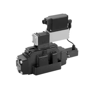
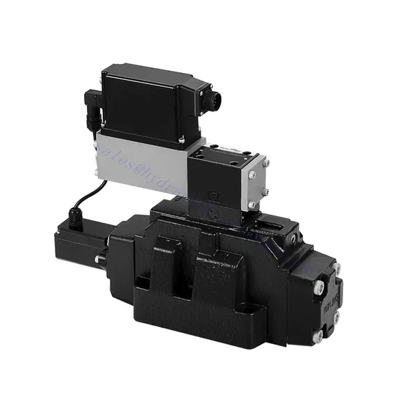
The 4WRLE series pilot-operated proportional directional hydraulic valve is a cutting-edge hydraulic component that revolutionizes fluid control in hydraulic systems. This valve combines pilot-operated technology with proportional directional control, offering precise flow regulation and exceptional efficiency.
The 4WRLE series pilot-operated proportional directional hydraulic valve elevates hydraulic control to new heights of precision and efficiency. With its pilot-operated technology and proportional directional control, this valve ensures accurate flow regulation, optimized energy consumption, and enhanced system performance. By following the recommended usage methods and maintenance guidelines, you can unleash the full potential of the 4WRLE series valve and achieve superior hydraulic control. Upgrade your hydraulic system today and experience the power of precision with the 4WRLE series pilot-operated proportional directional hydraulic valve.
4WRLE Series Pilot Operated Proportional Directional Hydraulic Valve Key Characteristics:
- Pilot Operated Technology:
- The 4WRLE series valve incorporates pilot-operated technology, allowing precise fluid flow control and pressure regulation.
- This technology enables efficient energy usage and reduces heat generation, resulting in improved overall system performance and reduced operating costs.
- Proportional Directional Control:
- With its proportional directional control capability, this valve provides accurate and balanced flow adjustment based on control signals.
- The proportional control allows for smooth and precise control of hydraulic actuators, enhancing system performance and minimizing wear and tear.
- Mångsidig funktionalitet:
- The 4WRLE series valve offers versatile control over fluid direction, making it suitable for a wide range of hydraulic applications.
- Whether it’s controlling cylinders, motors, or other hydraulic components, this valve ensures seamless activation and deactivation in different directions, enhancing system flexibility and adaptability.
- Hög flödeskapacitet:
- Designed to handle high flow rates, the 4WRLE series valve delivers exceptional performance even in demanding applications.
- Its robust construction and optimized flow channels ensure reliable operation and consistent flow control, meeting the requirements of high-power hydraulic systems.
4WRLE Series Pilot Operated Proportional Directional Hydraulic Valve Parameter:
NG6
| Allmän | |||||||
| Design | Spool valve, direct operated, with steel sleeve | ||||||
| Aktivering | Proportional solenoid with position control, OBE | ||||||
| Anslutningstyp | Subplate mounting, porting pattern according to ISO 4401-03-02-0-05 | ||||||
| Installationsposition | Any | ||||||
| Omgivningstemperaturintervall | ℃ | -20…+50 | |||||
| Vikt | kg | about 2.75 | |||||
| Maximum vibration resistance (test condition) | Max. 25 g, space vibration test in all directions (24h) | ||||||
| Hydraulisk (measured at p=100bar, with HLP46 at ϑoil = 40℃ ±5℃) | |||||||
| Tryckvätska | Mineral oil (HL, HLP)to DIN 51 524 | ||||||
| Viskositetsområde | rekommenderad | mm²/s | 20…100 | ||||
| max. tillåtet | mm²/s | 10…800 | |||||
| Tryckvätsketemperaturområde | ℃ | -20 to +70 | |||||
| Maximal tillåten föroreningsgrad av tryckvätska Renhetsklass enligt ISO 4406 (c) | Klass 18/16/13 | ||||||
| Rated flow (Δp = 35 bar per edge) | l/min | 2 | 4 | 12 | 24 | 40 | |
| Max. driftstryck | bar | Port A、B、P:315 | |||||
| Max. pressure | bar | Port T: 250 | |||||
| Leakage flow at 100 bar | Linear | cm³/min | <150 | <180 | <300 | <500 | <900; |
| Nonlinear | cm³/min | / | / | / | <300 | <450; | |
| Statisk/Dynamisk | |||||||
| Hysteres | % | ≤0.2 | |||||
| Actuating time for signal step 0 … 100% | ms | 10 | |||||
| Temperature drift | Zero shift < 1% at ΔT=40℃ | ||||||
| Zero compensation | Ex factory ±1% | ||||||
| Electric, control electronics integrated in the valve | |||||||
| Relative duty cycle | % | 100ED | |||||
| Skyddsgrad | IP65 | ||||||
| Connection | Plug-in connector 6P+PE, DIN 43563 | ||||||
| Supply voltage Terminal A Terminal B |
24VDCnom | ||||||
| min. 21VDC / max. 40VDC | |||||||
| 0V (ripple max. 2) | |||||||
| Fuse protection, external | AF | 2.5 | |||||
| nput, version “A1” Terminal D (UE) Terminal E |
Differential amplifier, Ri = 100 kΩ | ||||||
| 0…±10V | |||||||
| 0V | |||||||
| Input, version “F1” Terminal D (ID-E) Terminal E (ID-E) |
Load, Rsh = 200 Ω | ||||||
| 4…12…20mA | |||||||
| Current loop ID-E return | |||||||
| Test signal, version “A1” Terminal F (UTest) Terminal C |
LVDT | ||||||
| 0…±10V | |||||||
| Reference 0 V | |||||||
| Test signal, version “F1” Terminal F ( I F-C ) Terminal C ( I F-C ) |
LVDT signal 4 … (12) … 20 mA on external load 200 … 500 Ωmaximum | ||||||
| 4 … (12) … 20mA (output) | |||||||
| Current loop IF-C return | |||||||
| Adjustment | Calibrated before delivery, see characteristic curves | ||||||
NG10
| Allmän | |||||
| Design | Spool valve, directly operated, with steel sleeve | ||||
| Aktivering | Proportional solenoid with position control, OBE | ||||
| Anslutningstyp | Plate port, porting pattern (ISO 4401-05-04-0-05) | ||||
| Installationsposition | Any | ||||
| Omständigheter temperaturintervall | ℃ | -20…+50 | |||
| Vikt | kg | about 7.1 | |||
| Maximum vibration resistance (test condition) | Max. 25 g, space vibration test in all directions (24h) | ||||
| Hydraulic (measured with HLP 46, ϑoil =40℃ ±5℃) | |||||
| Tryckvätska | Hydraulic oil according to DIN 51524…535 | ||||
| Viskositetsområde | rekommenderad | mm²/s | 20…100 | ||
| Max. permitted | mm²/s | 10…800 | |||
| Tryckvätsketemperaturområde | ℃ | -20 to +70 | |||
| Max. admissible degree of contamination of the hydraulic fluid,cleanliness class according to ISO 4406 (c) | Klass 18/16/13 | ||||
| Rated flow(Δp = 35 bar per edge) | l/min | 50 | 100 | ||
| Max. driftstryck | bar | Port P A B: 315 | |||
| Max. pressure | bar | Port T: 250 | |||
| Leakage flow at 100 bar | Linear | cm³/min | <1200 | <1500 | |
| Nonlinear | cm³/min | <600 | <600 | ||
| Statisk/Dynamisk | |||||
| Hysteres | % | ≤0.2 | |||
| Actuating time for signal step 0 … 100% | ms | 25 | |||
| Temperature drift | Zero shift < 1% at ΔT=40℃ | ||||
| Zero compensation | Ex factory ±1% | ||||
| Electric, control electronics integrated in the valve | |||||
| Relative duty cycle | % | 100ED | |||
| Skyddsgrad | IP65(with mating connector mounted and locked ) | ||||
| Connection | Mating connector 6P+PE, DIN 43563 | ||||
| Supply voltage Terminal A Terminal B |
24VDCnom | ||||
| min. 21VDC / max. 40VDC | |||||
| Ripple max. 2 VDC | |||||
| Fuse protection, external | AF | 2.5 | |||
| Input, version “A1” Terminal D (UE) Terminal E |
Differential amplifier, Ri = 100 kΩ | ||||
| 0…±10V | |||||
| 0V | |||||
| Input, version “F1” Terminal D (ID-E) Terminal E (ID-E) |
Load, Rsh = 200 | ||||
| 4…12…20mA | |||||
| Current loop ID-E return | |||||
| Test signal, version “A1” Terminal F (UTesta) Terminal C |
LVDT | ||||
| 0…±10V | |||||
| Reference 0 V | |||||
| Test signal, version “F1” Terminal F ( I F-C ) Terminal C ( I F-C ) |
LVDT | ||||
| 4…20 mA output | |||||
| Current loop IF-C feedback | |||||
4WRLE Series Pilot Operated Proportional Directional Hydraulic Valve Advantages:
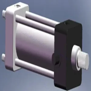
• Direct-acting servo solenoid valve with control piston and valve sleeve, with servo performance
• Single-side drive, optional, with power-off safety function
Control solenoid with built-in feedback and integrated amplifier board (OBE), factory preset
• Electrical connection 6P+PE signal input differential amplifier with interface, input optional A1: ±10V, or interface F1: 4…20mA (Rsh =200Ω)
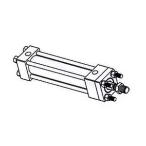
• Panel mounting: the mounting surface complies with ISO 4401-03-02
Usage Method Of 4WRLE Series Pilot Operated Proportional Directional Hydraulic Valve:
- Systembedömning:
- Evaluate your hydraulic system and define the specific flow and directional control requirements.
- Identify whether the 4WRLE series valve is compatible with your system based on factors such as flow capacity, pressure rating, and compatibility with your application.
- Ventilval:
- Select the appropriate variant of the 4WRLE series valve based on your system parameters, flow requirements, and directional control needs.
- Consider factors such as maximum flow rate, pressure rating, response time, and environmental operating conditions.
- Installation:
- Följ tillverkarens installationsanvisningar noggrant för att säkerställa korrekt inriktning och säker montering av ventilen.
- Create leak-free connections and ensure correct flow direction alignment to guarantee optimal performance.
- Integrering av styrsignaler:
- Anslut ventilens styrsignalledningar till en lämplig styrenhet, såsom en proportionalförstärkare eller elektronisk styrenhet.
- Ensure proper wiring and compatibility between the valve and control device to achieve accurate and responsive control.
How To Hook Up A Hydraulic Flow Control Valve?
To hook up a hydraulic flow control valve, follow these steps:
- Identifiera ventiltyp: Determine the specific type of flow control valve you are working with. Common types include needle valves, adjustable flow control valves, or pressure-compensated flow control valves. Ensure that the valve is suitable for your application and compatible with your hydraulic system.
- Samla nödvändiga verktyg och material: Collect the necessary tools and materials, including appropriate hydraulic fittings, adapters, hoses, and wrenches.
- Förbered hydraulsystemet: Shut down the hydraulic system and relieve any pressure in the system by activating the relief valve or retracting any hydraulic cylinders. This step is crucial for safety.
- Identifiera flödesriktning: Identify the flow direction in your hydraulic system. Typically, the flow direction is indicated by arrows on the hydraulic components. Ensure that you understand the correct flow direction before proceeding.
- Lokalisera installationspunkten: Determine the optimal location to install the flow control valve in your hydraulic system. Consider factors such as accessibility, proximity to the actuator or hydraulic component, and ease of adjustment.
- Montera ventilen: Securely mount the flow control valve in the chosen location using appropriate brackets or clamps. Ensure the valve is positioned correctly, aligning the inlet and outlet ports with the flow direction.
- Anslut inlopps- och utloppsportarna: Attach hydraulic hoses or tubing to the inlet and outlet ports of the flow control valve. Use suitable hydraulic fittings and adapters to create a leak-free connection. Tighten the connections using wrenches to ensure a secure fit, but avoid over-tightening.
- Adjust the Flow Control: Depending on the type of flow control valve, it may have adjustable features such as a needle valve or a flow control knob. Adjust the valve according to your desired flow rate or speed. Refer to the manufacturer’s instructions for specific adjustment procedures.
- Testa systemet: Once the flow control valve is installed and adjusted, slowly restore hydraulic system pressure. Test the system to ensure that the flow control valve is functioning correctly. Monitor the flow rate or speed of the hydraulic actuator to verify that it is within the desired range.
- Fine-tune and Monitor: Adjust the flow control valve to achieve the desired flow rate or speed. Regularly monitor the hydraulic system for leaks, pressure inconsistencies, or unusual behavior.
Fabrikens kapacitet och kapacitet:
(1) Montering
Vi har en förstklassig oberoende forsknings- och utvecklingsplattform. Verkstaden för tillverkning av hydraulcylindrar har fyra halvautomatiska monteringslinjer för lyftcylindrar och en automatisk monteringslinje för tiltcylindrar, med en planerad årlig produktionskapacitet på 1 miljon enheter. Specialcylinderverkstaden är utrustad med olika specifikationer för ett halvautomatiskt rengöringsmonteringssystem med en planerad årlig produktionskapacitet på 200 000 och utrustad med känd CNC-bearbetningsutrustning, ett fleroperationscenter, en specialutrustning för högprecisionscylindrar, en robotsvetsmaskin, en automatisk rengöringsmaskin, en automatisk cylindermonteringsmaskin och en automatisk produktionslinje för målning. Befintlig kritisk utrustning på mer än 300 set (set). Optimal allokering och effektiv användning av utrustningsresurser säkerställer produkternas noggrannhetskrav och uppfyller produkternas höga kvalitetsbehov.


(2) Maskinbearbetning
Bearbetningsverkstaden är utrustad med en specialanpassad svarvcentral för lutande räls, bearbetningscenter, höghastighetshönsmaskin, svetsrobot och annan relaterad utrustning, som kan hantera bearbetning av cylinderrör med en maximal innerdiameter på 400 mm och en maximal längd på 6 meter.

(3) Svetsning

(4) Målning och ytbehandling
Med små och medelstora cylindriska automatiska vattenbaserade färgbeläggningslinjer, för att uppnå automatisk robotlastning och lossning samt automatisk sprutning, är den designade kapaciteten 4000 stycken per skift;
Vi har även en halvautomatisk färgproduktionslinje för stora cylindrar som drivs av en släpkedja, med en designkapacitet på 60 lådor per skift.


(5) Testning
Vi har förstklassiga inspektionsanläggningar och testbäddar för att säkerställa att cylinderns prestanda uppfyller kraven.

Vi är en av de bästa tillverkarna av hydraulcylindrar. Vi kan erbjuda ett heltäckande utbud av hydraulcylindrar. Vi tillhandahåller även motsvarande jordbruksväxellådorVi har exporterat våra produkter till kunder över hela världen och fått ett gott rykte tack vare vår överlägsna produktkvalitet och kundservice. Vi välkomnar kunder både hemma och utomlands att kontakta oss för att förhandla affärer, utbyta information och samarbeta med oss!