
Σειρά 4WRPEH Αναλογική κατευθυντική υδραυλική βαλβίδα
Σειρά 4WRPEH Αναλογική κατευθυντική υδραυλική βαλβίδα
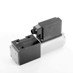
Η αναλογική κατευθυντική υδραυλική βαλβίδα σειράς 4WRPEH είναι ένα προηγμένο υδραυλικό εξάρτημα σχεδιασμένο για να παρέχει εξαιρετική ακρίβεια και έλεγχο σε υδραυλικά συστήματα. Με την καινοτόμο τεχνολογία αναλογικού κατευθυντικού ελέγχου, αυτή η βαλβίδα επιτρέπει την ακριβή ρύθμιση της ροής και τις ομαλές αλλαγές κατεύθυνσης.
Η αναλογική κατευθυντική υδραυλική βαλβίδα της σειράς 4WRPEH ενδυναμώνει τα υδραυλικά συστήματα με ακριβή έλεγχο ροής, ευέλικτη λειτουργικότητα και βελτιωμένη απόδοση. Η τεχνολογία αναλογικού κατευθυντικού ελέγχου εξασφαλίζει ακριβή και άμεση ρύθμιση ροής, ενώ η υψηλή χωρητικότητα ροής εγγυάται αξιόπιστη απόδοση ακόμη και σε απαιτητικές εφαρμογές. Ακολουθώντας τις συνιστώμενες μεθόδους χρήσης και τις οδηγίες συντήρησης, μπορείτε να μεγιστοποιήσετε τα οφέλη και τη μακροζωία της βαλβίδας της σειράς 4WRPEH, ανεβάζοντας το υδραυλικό σας σύστημα σε νέα επίπεδα ακρίβειας και ελέγχου. Αναβαθμίστε την υδραυλική σας εγκατάσταση σήμερα και ζήστε την ισχύ της αναλογικής κατευθυντικής υδραυλικής βαλβίδας της σειράς 4WRPEH.
Βασικά χαρακτηριστικά αναλογικής κατευθυντικής υδραυλικής βαλβίδας σειράς 4WRPEH:
- Αναλογικός κατευθυντικός έλεγχος:
- Η βαλβίδα σειράς 4WRPEH χρησιμοποιεί τεχνολογία αναλογικού κατευθυντικού ελέγχου τελευταίας τεχνολογίας, επιτρέποντας ακριβή και αναλογική ρύθμιση ροής με βάση τα σήματα ελέγχου.
- Αυτή η λειτουργία διασφαλίζει ακριβή και γρήγορο έλεγχο, με αποτέλεσμα βελτιωμένη απόδοση του συστήματος, μειωμένη κατανάλωση ενέργειας και αυξημένη παραγωγικότητα.
- Ευέλικτη λειτουργικότητα:
- Αυτή η βαλβίδα προσφέρει ευέλικτο έλεγχο της κατεύθυνσης του υδραυλικού υγρού, καθιστώντας την κατάλληλη για ένα ευρύ φάσμα εφαρμογών.
- Επιτρέπει την απρόσκοπτη ενεργοποίηση και απενεργοποίηση υδραυλικών εξαρτημάτων όπως κυλίνδρους, κινητήρες και ενεργοποιητές σε διαφορετικές κατευθύνσεις, ενισχύοντας την ευελιξία και την προσαρμοστικότητα του συστήματος.
- Υψηλή χωρητικότητα ροής:
- Η βαλβίδα σειράς 4WRPEH έχει σχεδιαστεί για να χειρίζεται υψηλούς ρυθμούς ροής, καθιστώντας την ιδανική για εφαρμογές που απαιτούν σημαντική υδραυλική ισχύ.
- Η στιβαρή κατασκευή του εξασφαλίζει αξιόπιστη απόδοση ακόμη και υπό απαιτητικές συνθήκες, παρέχοντας συνεπή και αποτελεσματικό έλεγχο ροής.
- Ακριβής μέτρηση:
- Με την τεχνολογία αναλογικού ελέγχου, αυτή η βαλβίδα προσφέρει ακριβή δοσολογία υδραυλικού υγρού, επιτρέποντας τον ακριβή έλεγχο και ρύθμιση των ρυθμών ροής.
- Αυτή η ακρίβεια βελτιώνει τη συνολική απόδοση του συστήματος και διασφαλίζει ακριβείς κινήσεις των υδραυλικών ενεργοποιητών.
Παράμετρος αναλογικής κατευθυντικής υδραυλικής βαλβίδας σειράς 4WRPEH:
NG6
| Γενικός | |||||||
| Σχέδιο | Βαλβίδα πηνίου, άμεσης λειτουργίας, με χαλύβδινο χιτώνιο | ||||||
| Κίνηση | Αναλογικό σωληνοειδές με έλεγχο θέσης, OBE | ||||||
| Τύπος σύνδεσης | Τοποθέτηση υποπλάκας, σχέδιο θύρας σύμφωνα με το πρότυπο ISO 4401-03-02-0-05 | ||||||
| Θέση εγκατάστασης | Κάθε | ||||||
| Εύρος θερμοκρασίας περιβάλλοντος | ℃ | -20…+50 | |||||
| Βάρος | Κιλά | περίπου 2,75 | |||||
| Μέγιστη αντοχή σε κραδασμούς (συνθήκη δοκιμής) | Μέγιστο 25 g, δοκιμή δόνησης χώρου προς όλες τις κατευθύνσεις (24 ώρες) | ||||||
| Υδραυλικός (μετρημένο στα p=100bar, με HLP46 σε ϑέλαιο = 40℃ ±5℃) | |||||||
| Ρευστό υπό πίεση | Ορυκτέλαιο (HL, HLP) σύμφωνα με το DIN 51 524 | ||||||
| Εύρος ιξώδους | συνιστάται | mm²/s | 20…100 | ||||
| μέγιστο επιτρεπόμενο | mm²/s | 10…800 | |||||
| Εύρος θερμοκρασίας ρευστού πίεσης | ℃ | -20 έως +70 | |||||
| Μέγιστος επιτρεπόμενος βαθμός μόλυνσης του ρευστού υπό πίεση Κατηγορία καθαρότητας σύμφωνα με το πρότυπο ISO 4406 (c) | Τάξη 18/16/13 | ||||||
| Ονομαστική ροή (Δp = 35 bar ανά ακμή) | Λ/λεπτό | 2 | 4 | 12 | 24 | 40 | |
| Μέγιστη λειτουργούσα πίεση | μπαρ | Λιμένας Α, Β, Π: 315 | |||||
| Μέγιστη πίεση | μπαρ | Λιμάνι Τ: 250 | |||||
| Ροή διαρροής στα 100 bar | Γραμμικός | cm³/λεπτό | <150 | <180 | <300 | <500 | <900; |
| Μη γραμμικό | cm³/λεπτό | / | / | / | <300 | <450; | |
| Στατικό/Δυναμικό | |||||||
| Υστέρηση | % | ≤0,2 | |||||
| Χρόνος ενεργοποίησης για το βήμα σήματος 0 … 100% | ms | 10 | |||||
| Μετατόπιση θερμοκρασίας | Μηδενική μετατόπιση < 1% σε ΔT=40℃ | ||||||
| Μηδενική αποζημίωση | Από το εργοστάσιο ±1% | ||||||
| Ηλεκτρικά, ηλεκτρονικά ελέγχου ενσωματωμένα στη βαλβίδα | |||||||
| Σχετικός κύκλος λειτουργίας | % | 100ED | |||||
| Βαθμός προστασίας | IP65 | ||||||
| Σύνδεση | Βύσμα σύνδεσης 6P+PE, DIN 43563 | ||||||
| Τάση τροφοδοσίας Τερματικός σταθμός Α Τερματικός σταθμός Β |
24VDCόνομα | ||||||
| ελάχ. 21VDC / μέγ. 40VDC | |||||||
| 0V (μέγιστο 2 κυματισμός) | |||||||
| Προστασία με ασφάλεια, εξωτερική | AF | 2.5 | |||||
| είσοδος, έκδοση «A1» Τερματικός σταθμός D (Uμι) Τερματικός σταθμός Ε |
Διαφορικός ενισχυτής, Ri = 100 kΩ | ||||||
| 0…±10V | |||||||
| 0V | |||||||
| Είσοδος, έκδοση «F1» Τερματικός σταθμός D (ID-E) Τερματικός σταθμός Ε (ID-E) |
Φορτίο, Rσς = 200 Ω | ||||||
| 4…12…20mA | |||||||
| Βρόχος ρεύματος ΙΔΕ απόδοση | |||||||
| Σήμα δοκιμής, έκδοση «A1» Τερματικός σταθμός F (UTest) Τερματικός σταθμός Γ |
LVDT | ||||||
| 0…±10V | |||||||
| Αναφορά 0 V | |||||||
| Σήμα δοκιμής, έκδοση «F1» Τερματικός σταθμός F (I) Ποδοσφαιρική Ομοσπονδία ) Τερματικός σταθμός C (I) Ποδοσφαιρική Ομοσπονδία ) |
Σήμα LVDT 4 … (12) … 20 mA σε εξωτερικό φορτίο 200 … 500 Ωμέγιστο | ||||||
| 4 … (12) … 20mA (έξοδος) | |||||||
| Βρόχος ρεύματος ΙΠοδοσφαιρική Ομοσπονδία απόδοση | |||||||
| Προσαρμογή | Βαθμονομημένο πριν από την παράδοση, βλέπε χαρακτηριστικές καμπύλες | ||||||
NG10
| Γενικός | |||||
| Σχέδιο | Βαλβίδα πηνίου, άμεσης λειτουργίας, με χαλύβδινο χιτώνιο | ||||
| Κίνηση | Αναλογικό σωληνοειδές με έλεγχο θέσης, OBE | ||||
| Τύπος σύνδεσης | Θύρα πλάκας, μοτίβο θυρών (ISO 4401-05-04-0-05) | ||||
| Θέση εγκατάστασης | Κάθε | ||||
| Εύρος θερμοκρασίας περιστάσεων | ℃ | -20…+50 | |||
| Βάρος | Κιλά | περίπου 7,1 | |||
| Μέγιστη αντοχή σε κραδασμούς (συνθήκη δοκιμής) | Μέγιστο 25 g, δοκιμή δόνησης χώρου προς όλες τις κατευθύνσεις (24 ώρες) | ||||
| Υδραυλικό (μετρημένο με HLP 46, ϑέλαιο =40℃ ±5℃) | |||||
| Ρευστό υπό πίεση | Υδραυλικό λάδι σύμφωνα με το πρότυπο DIN 51524…535 | ||||
| Εύρος ιξώδους | συνιστάται | mm²/s | 20…100 | ||
| Μέγιστο επιτρεπόμενο | mm²/s | 10…800 | |||
| Εύρος θερμοκρασίας ρευστού πίεσης | ℃ | -20 έως +70 | |||
| Μέγιστος επιτρεπόμενος βαθμός μόλυνσης του υδραυλικού υγρού, κατηγορία καθαριότητας σύμφωνα με το πρότυπο ISO 4406 (c) | Τάξη 18/16/13 | ||||
| Ονομαστική ροή (Δp = 35 bar ανά ακμή) | Λ/λεπτό | 50 | 100 | ||
| Μέγιστη λειτουργούσα πίεση | μπαρ | Λιμάνι PAB: 315 | |||
| Μέγιστη πίεση | μπαρ | Λιμάνι Τ: 250 | |||
| Ροή διαρροής στα 100 bar | Γραμμικός | cm³/λεπτό | <1200 | <1500 | |
| Μη γραμμικό | cm³/λεπτό | <600 | <600 | ||
| Στατικό/Δυναμικό | |||||
| Υστέρηση | % | ≤0,2 | |||
| Χρόνος ενεργοποίησης για το βήμα σήματος 0 … 100% | ms | 25 | |||
| Μετατόπιση θερμοκρασίας | Μηδενική μετατόπιση < 1% σε ΔT=40℃ | ||||
| Μηδενική αποζημίωση | Από το εργοστάσιο ±1% | ||||
| Ηλεκτρικά, ηλεκτρονικά ελέγχου ενσωματωμένα στη βαλβίδα | |||||
| Σχετικός κύκλος λειτουργίας | % | 100ED | |||
| Βαθμός προστασίας | IP65 (με τοποθετημένο και κλειδωμένο σύνδεσμο ζευγαρώματος) | ||||
| Σύνδεση | Συνδετικός σύνδεσμος 6P+PE, DIN 43563 | ||||
| Τάση τροφοδοσίας Τερματικός σταθμός Α Τερματικός σταθμός Β |
24VDCόνομα | ||||
| ελάχ. 21VDC / μέγ. 40VDC | |||||
| Μέγιστη τάση κύματος 2 VDC | |||||
| Προστασία με ασφάλεια, εξωτερική | AF | 2.5 | |||
| Είσοδος, έκδοση «A1» Τερματικός σταθμός D (Uμι) Τερματικός σταθμός Ε |
Διαφορικός ενισχυτής, Ri = 100 kΩ | ||||
| 0…±10V | |||||
| 0V | |||||
| Είσοδος, έκδοση «F1» Τερματικός σταθμός D (IΔΕ) Τερματικός σταθμός Ε (Ι)ΔΕ) |
Φορτίο, Rσς = 200 | ||||
| 4…12…20mA | |||||
| Βρόχος ρεύματος ΙΔΕ απόδοση | |||||
| Σήμα δοκιμής, έκδοση «A1» Τερματικό F (UΔοκιμή) Τερματικός σταθμός Γ |
LVDT | ||||
| 0…±10V | |||||
| Αναφορά 0 V | |||||
| Σήμα δοκιμής, έκδοση «F1» Τερματικός σταθμός F (I) Ποδοσφαιρική Ομοσπονδία ) Τερματικός σταθμός C (I) Ποδοσφαιρική Ομοσπονδία ) |
LVDT | ||||
| Έξοδος 4…20 mA | |||||
| Βρόχος ρεύματος ΙΠοδοσφαιρική Ομοσπονδία ανατροφοδότηση | |||||
Πλεονεκτήματα αναλογικής κατευθυντικής υδραυλικής βαλβίδας σειράς 4WRPEH:
• Σερβοηλεκτροβαλβίδα άμεσης δράσης με έμβολο ελέγχου και χιτώνιο βαλβίδας, με απόδοση σερβο
• Μονόπλευρη κίνηση, προαιρετική με λειτουργία ασφαλείας απενεργοποίησης
Ηλεκτρομαγνητική βαλβίδα ελέγχου με ενσωματωμένη ανάδραση και ενσωματωμένη πλακέτα ενισχυτή (OBE), εργοστασιακά προκαθορισμένη
• Ηλεκτρική σύνδεση Διαφορικός ενισχυτής εισόδου σήματος 6P+PE με διεπαφή, είσοδος προαιρετική A1: ±10V ή διεπαφή F1: 4…20mA (Rsh =200Ω)
• Τοποθέτηση σε πάνελ, η επιφάνεια τοποθέτησης συμμορφώνεται με το πρότυπο ISO 4401-03-02
Μέθοδος χρήσης αναλογικής κατευθυντικής υδραυλικής βαλβίδας σειράς 4WRPEH :
- Αξιολόγηση Συστήματος:
- Αξιολογήστε το υδραυλικό σας σύστημα και προσδιορίστε τις συγκεκριμένες απαιτήσεις ελέγχου ροής και κατεύθυνσης.
- Προσδιορίστε εάν η βαλβίδα σειράς 4WRPEH είναι κατάλληλη με βάση την ικανότητα ροής, την ονομαστική πίεση και τη συμβατότητά της με το σύστημά σας.
- Επιλογή βαλβίδας:
- Επιλέξτε την κατάλληλη παραλλαγή της βαλβίδας σειράς 4WRPEH με βάση τις παραμέτρους του συστήματός σας, τις απαιτήσεις ροής και τις ανάγκες κατευθυντικού ελέγχου.
- Λάβετε υπόψη παράγοντες όπως η μέγιστη παροχή, η ονομαστική πίεση, ο χρόνος απόκρισης και οι συνθήκες λειτουργίας.
- Εγκατάσταση:
- Ακολουθήστε προσεκτικά τις οδηγίες εγκατάστασης του κατασκευαστή, διασφαλίζοντας την σωστή ευθυγράμμιση και την ασφαλή τοποθέτηση της βαλβίδας.
- Κάντε συνδέσεις χωρίς διαρροές και βεβαιωθείτε για τη σωστή ευθυγράμμιση της κατεύθυνσης ροής για να εξασφαλίσετε βέλτιστη απόδοση.
- Σύνδεση σήματος ελέγχου:
- Συνδέστε τα καλώδια σήματος ελέγχου της βαλβίδας σε μια κατάλληλη συσκευή ελέγχου, όπως έναν αναλογικό ενισχυτή ή μια ηλεκτρονική μονάδα ελέγχου.
- Βεβαιωθείτε για την σωστή καλωδίωση και συμβατότητα μεταξύ της βαλβίδας και της συσκευής ελέγχου για ακριβή και άμεσο έλεγχο.
Πώς να συνδέσετε δύο υδραυλικές βαλβίδες μεταξύ τους;
Η σύνδεση δύο υδραυλικών βαλβίδων απαιτεί προσεκτική εξέταση των τύπων βαλβίδων, των λειτουργιών τους και των συγκεκριμένων απαιτήσεων του υδραυλικού συστήματος. Ακολουθούν γενικές οδηγίες για τον τρόπο σύνδεσης δύο υδραυλικών βαλβίδων:
- Προσδιορίστε τους τύπους βαλβίδων:
- Προσδιορίστε τους τύπους βαλβίδων με τις οποίες εργάζεστε, όπως βαλβίδες κατευθυντικού ελέγχου, βαλβίδες ελέγχου πίεσης, βαλβίδες ελέγχου ροής ή οποιεσδήποτε άλλες συγκεκριμένες βαλβίδες που απαιτούνται για το σύστημά σας.
- Βεβαιωθείτε ότι και οι δύο βαλβίδες είναι συμβατές ως προς το μέγεθος, την ονομαστική πίεση, την ικανότητα ροής και τη λειτουργία.
- Κατανόηση των λειτουργιών της βαλβίδας:
- Εξοικειωθείτε με τις λειτουργίες κάθε βαλβίδας. Για παράδειγμα, οι βαλβίδες κατευθυντικού ελέγχου ρυθμίζουν την κατεύθυνση ροής του ρευστού, οι βαλβίδες ελέγχου πίεσης ελέγχουν την πίεση του συστήματος και οι βαλβίδες ελέγχου ροής διαχειρίζονται τους ρυθμούς ροής.
- Προσδιορίστε πώς ο συνδυασμός αυτών των βαλβίδων θα συμβάλει στην επίτευξη της επιθυμητής λειτουργίας του υδραυλικού συστήματος.
- Προσδιορίστε την τοποθέτηση της βαλβίδας:
- Αποφασίστε σε ποιο σημείο του υδραυλικού συστήματος θέλετε να εγκαταστήσετε τις δύο βαλβίδες. Λάβετε υπόψη παράγοντες όπως η διαδρομή ροής ρευστού, οι απαιτήσεις πίεσης και η επιθυμητή ακολουθία ελέγχου.
- Βεβαιωθείτε ότι η τοποθέτηση της βαλβίδας επιτρέπει την κατάλληλη ροή υγρού και την προσβασιμότητα για συντήρηση και λειτουργία.
- Σύνδεση θυρών βαλβίδας:
- Προσδιορίστε τις θύρες εισόδου και εξόδου κάθε βαλβίδας. Αυτές οι θύρες ενδέχεται να φέρουν ετικέτα ή να αναφέρονται στην τεκμηρίωση της βαλβίδας.
- Χρησιμοποιήστε κατάλληλα υδραυλικά εξαρτήματα, προσαρμογείς ή συνδετήρες για να συνδέσετε τις θύρες των δύο βαλβίδων μεταξύ τους.
- Εξασφαλίστε μια ασφαλή και χωρίς διαρροές σύνδεση χρησιμοποιώντας κατάλληλα υλικά στεγανοποίησης, όπως δακτυλίους Ο ή στεγανωτικά σπειρωμάτων.
- Λάβετε υπόψη τις αλληλεπιδράσεις των βαλβίδων:
- Αξιολογήστε πώς η αλληλεπίδραση μεταξύ των δύο βαλβίδων θα επηρεάσει τη συνολική απόδοση του υδραυλικού συστήματος.
- Βεβαιωθείτε ότι η συνδυασμένη λειτουργία των βαλβίδων δεν δημιουργεί συγκρούσεις ή δεν έχει ως αποτέλεσμα ακούσιες συνέπειες, όπως αιχμές πίεσης, περιορισμούς ροής ή ακούσιες κινήσεις.
- Ενσωμάτωση σήματος ελέγχου:
- Εάν οι βαλβίδες απαιτούν σήματα ελέγχου, όπως ηλεκτρικά ή πνευματικά σήματα, προσδιορίστε πώς θα ενσωματωθούν αυτά τα σήματα.
- Συνδέστε τις γραμμές σήματος ελέγχου και των δύο βαλβίδων στις κατάλληλες συσκευές ελέγχου, όπως μονάδες υδραυλικού ελέγχου, ηλεκτρονικές μονάδες ελέγχου ή μοχλούς χειροκίνητου ελέγχου.
- Βεβαιωθείτε για την κατάλληλη καλωδίωση, συμβατότητα και συγχρονισμό μεταξύ των συσκευών ελέγχου και των βαλβίδων, ώστε να επιτευχθεί ο επιθυμητός έλεγχος και συντονισμός.
- Δοκιμή και ρύθμιση:
- Αφού συνδέσετε τις βαλβίδες μεταξύ τους, ελέγξτε διεξοδικά το υδραυλικό σύστημα για να διασφαλίσετε την ορθή λειτουργία του.
- Παρακολουθήστε το σύστημα για τυχόν προβλήματα, όπως διαρροές, υπερβολικές πτώσεις πίεσης ή απροσδόκητη συμπεριφορά.
- Κάντε τις απαραίτητες προσαρμογές, όπως βελτιστοποίηση των ρυθμίσεων ελέγχου ή τροποποίηση της τοποθέτησης των βαλβίδων, εάν απαιτείται.
Ικανότητα & χωρητικότητα του εργοστασίου:
(1) Συναρμολόγηση
Διαθέτουμε μια πρώτης τάξεως ανεξάρτητη πλατφόρμα συναρμολόγησης έρευνας και ανάπτυξης. Το εργαστήριο παραγωγής υδραυλικών κυλίνδρων διαθέτει τέσσερις ημιαυτόματες γραμμές συναρμολόγησης ανυψωτικών κυλίνδρων και μία αυτόματη γραμμή συναρμολόγησης κυλίνδρων κλίσης, με σχεδιασμένη ετήσια παραγωγική ικανότητα 1 εκατομμυρίου τεμαχίων. Το εργαστήριο ειδικών κυλίνδρων είναι εξοπλισμένο με διάφορες προδιαγραφές ενός ημιαυτόματου συστήματος συναρμολόγησης καθαρισμού με σχεδιασμένη ετήσια παραγωγική ικανότητα 200.000 και εξοπλισμένο με διάσημο εξοπλισμό κατεργασίας CNC, ένα κέντρο κατεργασίας, έναν ειδικό εξοπλισμό επεξεργασίας κυλίνδρων υψηλής ακρίβειας, μια μηχανή συγκόλλησης ρομπότ, μια αυτόματη μηχανή καθαρισμού, μια αυτόματη μηχανή συναρμολόγησης κυλίνδρων και μια αυτόματη γραμμή παραγωγής βαφής. Υφιστάμενος κρίσιμος εξοπλισμός άνω των 300 σετ (σετ). Η βέλτιστη κατανομή και η αποτελεσματική χρήση των πόρων του εξοπλισμού διασφαλίζουν τις απαιτήσεις ακρίβειας των προϊόντων και καλύπτουν τις ανάγκες υψηλής ποιότητας των προϊόντων.


(2) Κατεργασία
Το εργαστήριο κατεργασίας είναι εξοπλισμένο με ένα προσαρμοσμένο κέντρο τόρνευσης με κεκλιμένη ράγα, κέντρο κατεργασίας, μηχανή λείανσης υψηλής ταχύτητας, ρομπότ συγκόλλησης και άλλο συναφή εξοπλισμό, το οποίο μπορεί να χειριστεί την επεξεργασία κυλινδρικών σωλήνων με μέγιστη εσωτερική διάμετρο 400 mm και μέγιστο μήκος 6 μέτρων.

(3) Συγκόλληση

(4) Βαφή και επίστρωση
Με μικρές και μεσαίες αυτόματες γραμμές επίστρωσης χρωμάτων με βάση το νερό, για την επίτευξη αυτόματης φόρτωσης και εκφόρτωσης ρομπότ και αυτόματου ψεκασμού, η ικανότητα σχεδιασμού 4000 τεμαχίων ανά βάρδια,
Διαθέτουμε επίσης μια ημιαυτόματη γραμμή παραγωγής χρωμάτων για μεγάλους κυλίνδρους που τροφοδοτείται από μια αλυσίδα ισχύος, με δυνατότητα σχεδιασμού 60 κιβωτίων ανά βάρδια.


(5) Δοκιμές
Διαθέτουμε πρώτης τάξεως εγκαταστάσεις επιθεώρησης και δοκιμαστικές κλίνες για να διασφαλίσουμε ότι η απόδοση του κυλίνδρου ανταποκρίνεται στις απαιτήσεις.

Είμαστε ένας από τους καλύτερους κατασκευαστές υδραυλικών κυλίνδρων. Μπορούμε να προσφέρουμε ολοκληρωμένους υδραυλικούς κυλίνδρους. Παρέχουμε επίσης αντίστοιχους γεωργικά κιβώτια ταχυτήτων. Έχουμε εξάγει τα προϊόντα μας σε πελάτες σε όλο τον κόσμο και έχουμε κερδίσει μια καλή φήμη λόγω της ανώτερης ποιότητας των προϊόντων μας και της εξυπηρέτησης μετά την πώληση. Καλωσορίζουμε τους πελάτες στο εσωτερικό και στο εξωτερικό να επικοινωνήσουν μαζί μας για να διαπραγματευτούν τις επιχειρήσεις, να ανταλλάξουν πληροφορίες και να συνεργαστείτε μαζί μας!


