
4WRPEH Series Proportional Directional Hydraulic Valve
4WRPEH Series Proportional Directional Hydraulic Valve
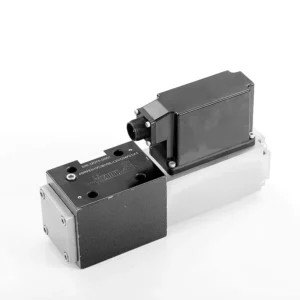
The 4WRPEH series proportional directional hydraulic valve is an advanced hydraulic component designed to deliver exceptional precision and control in hydraulic systems. With its innovative proportional directional control technology, this valve enables accurate flow regulation and smooth directional changes.
The 4WRPEH series proportional directional hydraulic valve empowers hydraulic systems with precise flow control, versatile functionality, and enhanced efficiency. Its proportional directional control technology ensures accurate and responsive flow adjustment, while the high flow capacity guarantees reliable performance even in demanding applications. By following the recommended usage methods and maintenance guidelines, you can maximize the benefits and longevity of the 4WRPEH series valve, elevating your hydraulic system to new levels of precision and control. Upgrade your hydraulic setup today and experience the power of the 4WRPEH series proportional directional hydraulic valve.
4WRPEH Series Proportional Directional Hydraulic Valve Key Characteristics:
- Proportional Directional Control:
- The 4WRPEH series valve utilizes state-of-the-art proportional directional control technology, allowing precise and proportional flow adjustment based on control signals.
- 该功能可确保精确、灵敏的控制,从而提高系统性能、降低能耗并提高生产效率。
- 多功能:
- 该阀门可灵活控制液压流体方向,适用于多种应用。
- 它能够无缝地激活和停用液压元件(如油缸、马达和执行器)的不同方向,从而增强系统的灵活性和适应性。
- 高流量:
- The 4WRPEH series valve is engineered to handle high flow rates, making it ideal for applications that require substantial hydraulic power.
- 其坚固的结构确保即使在苛刻的条件下也能可靠运行,提供稳定高效的流量控制。
- Precise Metering:
- With its proportional control technology, this valve offers precise metering of hydraulic fluid, allowing for accurate control and regulation of flow rates.
- This precision enhances overall system performance and ensures precise movements of hydraulic actuators.
4WRPEH Series Proportional Directional Hydraulic Valve Parameter:
NG6
| 一般的 | |||||||
| 设计 | Spool valve, direct operated, with steel sleeve | ||||||
| 驱动 | Proportional solenoid with position control, OBE | ||||||
| 连接类型 | Subplate mounting, porting pattern according to ISO 4401-03-02-0-05 | ||||||
| 安装位置 | Any | ||||||
| 环境温度范围 | ℃ | -20…+50 | |||||
| 重量 | 公斤 | about 2.75 | |||||
| Maximum vibration resistance (test condition) | Max. 25 g, space vibration test in all directions (24h) | ||||||
| 液压 (measured at p=100bar, with HLP46 at ϑoil = 40℃ ±5℃) | |||||||
| 压力流体 | Mineral oil (HL, HLP)to DIN 51 524 | ||||||
| 粘度范围 | 受到推崇的 | 毫米²/秒 | 20…100 | ||||
| 最大允许值 | 毫米²/秒 | 10…800 | |||||
| 压力流体温度范围 | ℃ | -20 至 +70 | |||||
| 压力流体的最大允许污染程度 纯度等级符合 ISO 4406 (c) | 18/16/13班 | ||||||
| Rated flow (Δp = 35 bar per edge) | 升/分钟 | 2 | 4 | 12 | 24 | 40 | |
| 最大工作压力 | 酒吧 | Port A、B、P:315 | |||||
| Max. pressure | 酒吧 | Port T: 250 | |||||
| Leakage flow at 100 bar | Linear | cm³/min | <150 | <180 | <300 | <500 | <900; |
| Nonlinear | cm³/min | / | / | / | <300 | <450; | |
| 静态/动态 | |||||||
| 滞后 | % | ≤0.2 | |||||
| Actuating time for signal step 0 … 100% | 多发性硬化症 | 10 | |||||
| Temperature drift | Zero shift < 1% at ΔT=40℃ | ||||||
| Zero compensation | Ex factory ±1% | ||||||
| Electric, control electronics integrated in the valve | |||||||
| Relative duty cycle | % | 100ED | |||||
| 保护程度 | IP65 | ||||||
| 联系 | Plug-in connector 6P+PE, DIN 43563 | ||||||
| Supply voltage Terminal A Terminal B |
24VDCnom | ||||||
| min. 21VDC / max. 40VDC | |||||||
| 0V (ripple max. 2) | |||||||
| Fuse protection, external | AF | 2.5 | |||||
| nput, version “A1” Terminal D (UE) Terminal E |
Differential amplifier, Ri = 100 kΩ | ||||||
| 0…±10V | |||||||
| 0V | |||||||
| Input, version “F1” Terminal D (ID-E) Terminal E (ID-E) |
Load, Rsh = 200 Ω | ||||||
| 4…12…20mA | |||||||
| Current loop ID-E return | |||||||
| Test signal, version “A1” Terminal F (UTest) Terminal C |
LVDT | ||||||
| 0…±10V | |||||||
| Reference 0 V | |||||||
| Test signal, version “F1” Terminal F ( I F-C ) Terminal C ( I F-C ) |
LVDT signal 4 … (12) … 20 mA on external load 200 … 500 Ωmaximum | ||||||
| 4 … (12) … 20mA (output) | |||||||
| Current loop IF-C return | |||||||
| Adjustment | Calibrated before delivery, see characteristic curves | ||||||
NG10
| 一般的 | |||||
| 设计 | Spool valve, directly operated, with steel sleeve | ||||
| 驱动 | Proportional solenoid with position control, OBE | ||||
| 连接类型 | Plate port, porting pattern (ISO 4401-05-04-0-05) | ||||
| 安装位置 | Any | ||||
| 环境温度范围 | ℃ | -20…+50 | |||
| 重量 | 公斤 | about 7.1 | |||
| Maximum vibration resistance (test condition) | Max. 25 g, space vibration test in all directions (24h) | ||||
| Hydraulic (measured with HLP 46, ϑoil =40℃ ±5℃) | |||||
| 压力流体 | Hydraulic oil according to DIN 51524…535 | ||||
| 粘度范围 | 受到推崇的 | 毫米²/秒 | 20…100 | ||
| Max. permitted | 毫米²/秒 | 10…800 | |||
| 压力流体温度范围 | ℃ | -20 至 +70 | |||
| Max. admissible degree of contamination of the hydraulic fluid,cleanliness class according to ISO 4406 (c) | 18/16/13班 | ||||
| Rated flow(Δp = 35 bar per edge) | 升/分钟 | 50 | 100 | ||
| 最大工作压力 | 酒吧 | Port P A B: 315 | |||
| Max. pressure | 酒吧 | Port T: 250 | |||
| Leakage flow at 100 bar | Linear | cm³/min | <1200 | <1500 | |
| Nonlinear | cm³/min | <600 | <600 | ||
| 静态/动态 | |||||
| 滞后 | % | ≤0.2 | |||
| Actuating time for signal step 0 … 100% | 多发性硬化症 | 25 | |||
| Temperature drift | Zero shift < 1% at ΔT=40℃ | ||||
| Zero compensation | Ex factory ±1% | ||||
| Electric, control electronics integrated in the valve | |||||
| Relative duty cycle | % | 100ED | |||
| 保护程度 | IP65(with mating connector mounted and locked ) | ||||
| 联系 | Mating connector 6P+PE, DIN 43563 | ||||
| Supply voltage Terminal A Terminal B |
24VDCnom | ||||
| min. 21VDC / max. 40VDC | |||||
| Ripple max. 2 VDC | |||||
| Fuse protection, external | AF | 2.5 | |||
| Input, version “A1” Terminal D (UE) Terminal E |
Differential amplifier, Ri = 100 kΩ | ||||
| 0…±10V | |||||
| 0V | |||||
| Input, version “F1” Terminal D (ID-E) Terminal E (ID-E) |
Load, Rsh = 200 | ||||
| 4…12…20mA | |||||
| Current loop ID-E return | |||||
| Test signal, version “A1” Terminal F (U测试) Terminal C |
LVDT | ||||
| 0…±10V | |||||
| Reference 0 V | |||||
| Test signal, version “F1” Terminal F ( I F-C ) Terminal C ( I F-C ) |
LVDT | ||||
| 4…20 mA output | |||||
| Current loop IF-C feedback | |||||
4WRPEH Series Proportional Directional Hydraulic Valve Advantages:
• Direct-acting servo solenoid valve with control piston and valve sleeve, with servo performance
• Single-side drive, optional with power-off safety function
Control solenoid with built-in feedback and integrated amplifier board (OBE), factory preset
• Electrical connection 6P+PE signal input differential amplifier with interface, input optional A1: ±10V, or interface F1: 4…20mA (Rsh =200Ω)
• Panel mounting, the mounting surface complies with ISO 4401-03-02
Usage Method Of 4WRPEH Series Proportional Directional Hydraulic Valve :
- 系统评估:
- 评估您的液压系统,并确定具体的流量和方向控制要求。
- Determine if the 4WRPEH series valve is suitable based on its flow capacity, pressure rating, and compatibility with your system.
- 阀门选择:
- Select the appropriate variant of the 4WRPEH series valve based on your system parameters, flow requirements, and directional control needs.
- 考虑最大流量、压力等级、响应时间和操作条件等因素。
- 安装:
- 请仔细按照制造商的安装说明进行操作,确保阀门正确对准并牢固安装。
- Make leak-free connections and ensure correct flow direction alignment to guarantee optimal performance.
- 控制信号连接:
- 将阀门的控制信号线连接到合适的控制装置,例如比例放大器或电子控制单元。
- 确保阀门与控制装置之间接线正确且兼容,以实现精确、灵敏的控制。
How To Hook Two Hydraulic Valves Together?
Hooking two hydraulic valves together requires careful consideration of the valve types, their functions, and the specific hydraulic system requirements. Here are general guidelines on how to hook two hydraulic valves together:
- Identify Valve Types:
- Determine the types of valves you are working with, such as directional control valves, pressure control valves, flow control valves, or any other specific valves required for your system.
- Ensure that both valves are compatible in terms of size, pressure ratings, flow capacity, and function.
- Understand Valve Functions:
- Familiarize yourself with the functions of each valve. For example, directional control valves regulate fluid flow direction, pressure control valves control system pressure, and flow control valves manage flow rates.
- Determine how the combination of these valves will contribute to achieving the desired hydraulic system operation.
- Determine Valve Placement:
- Decide where in the hydraulic system you want to install the two valves. Consider factors such as fluid flow path, pressure requirements, and the desired control sequence.
- Ensure that the valve placement allows for proper fluid flow and accessibility for maintenance and operation.
- Connect Valve Ports:
- Identify the inlet and outlet ports of each valve. These ports may be labeled or indicated in the valve documentation.
- Use appropriate hydraulic fittings, adapters, or connectors to connect the ports of the two valves together.
- Ensure a secure and leak-free connection by using suitable sealing materials, such as O-rings or thread sealants.
- Consider Valve Interactions:
- Evaluate how the interaction between the two valves will affect the hydraulic system’s overall performance.
- Ensure that the combined operation of the valves does not create conflicts or result in unintended consequences, such as pressure spikes, flow restrictions, or unintended movements.
- Control Signal Integration:
- If the valves require control signals, such as electrical or pneumatic signals, determine how these signals will be integrated.
- Connect the control signal lines of both valves to the appropriate control devices, such as hydraulic control modules, electronic control units, or manual control levers.
- Ensure proper wiring, compatibility, and synchronization between the control devices and the valves to achieve the desired control and coordination.
- Test and Adjust:
- After hooking the valves together, thoroughly test the hydraulic system to ensure proper operation.
- Monitor the system for any issues, such as leaks, excessive pressure drops, or unexpected behavior.
- Make necessary adjustments, such as fine-tuning control settings or modifying valve placement if required.
工厂的能力和产能:
(1) 装配
我们拥有一流的自主研发装配平台。液压油缸生产车间拥有 4 条半自动提升油缸装配线和 1 条全自动倾斜油缸装配线,设计年生产能力 100 万支。特种油缸车间配备了各种规格的半自动清洗装配系统,设计年生产能力 20 万只,并配备了知名数控加工设备、加工中心、高精度油缸加工专用设备、机器人焊接机、自动清洗机、油缸自动装配机、自动喷漆生产线等。现有关键设备 300 多台(套)。设备资源的优化配置和高效利用,保证了产品的精度要求,满足了产品的高质量需求。


(2) 机加工
加工车间配备了定制的斜轨车削中心、加工中心、高速珩磨机、焊接机器人及其他相关设备,可加工最大内径 400 毫米、最大长度 6 米的气缸管。

(3) 焊接

(4) 油漆和涂料
配备中小型圆筒自动水性漆喷涂线,实现机器人自动上下料和自动喷涂,设计产能为每班 4000 件;
我们还拥有一条由动力链驱动的大型油缸半自动喷漆生产线,设计产能为每班 60 箱。


(5) 测试
我们拥有一流的检验设施和试验台,确保气缸的性能符合要求。

我们是最好的液压缸制造商之一。我们能够提供全面的液压缸。我们还提供相应的 农用齿轮箱凭借卓越的产品质量和售后服务,我们的产品远销世界各地,赢得了良好的声誉。我们欢迎国内外客户与我们联系洽谈业务、交流信息,并 与我们合作!


